Bose Lifestyle 28 Installation guide - Page 19
Making the temporary headset connection before connecting to power, Connecting the system to power - rear setup
 |
View all Bose Lifestyle 28 manuals
Add to My Manuals
Save this manual to your list of manuals |
Page 19 highlights
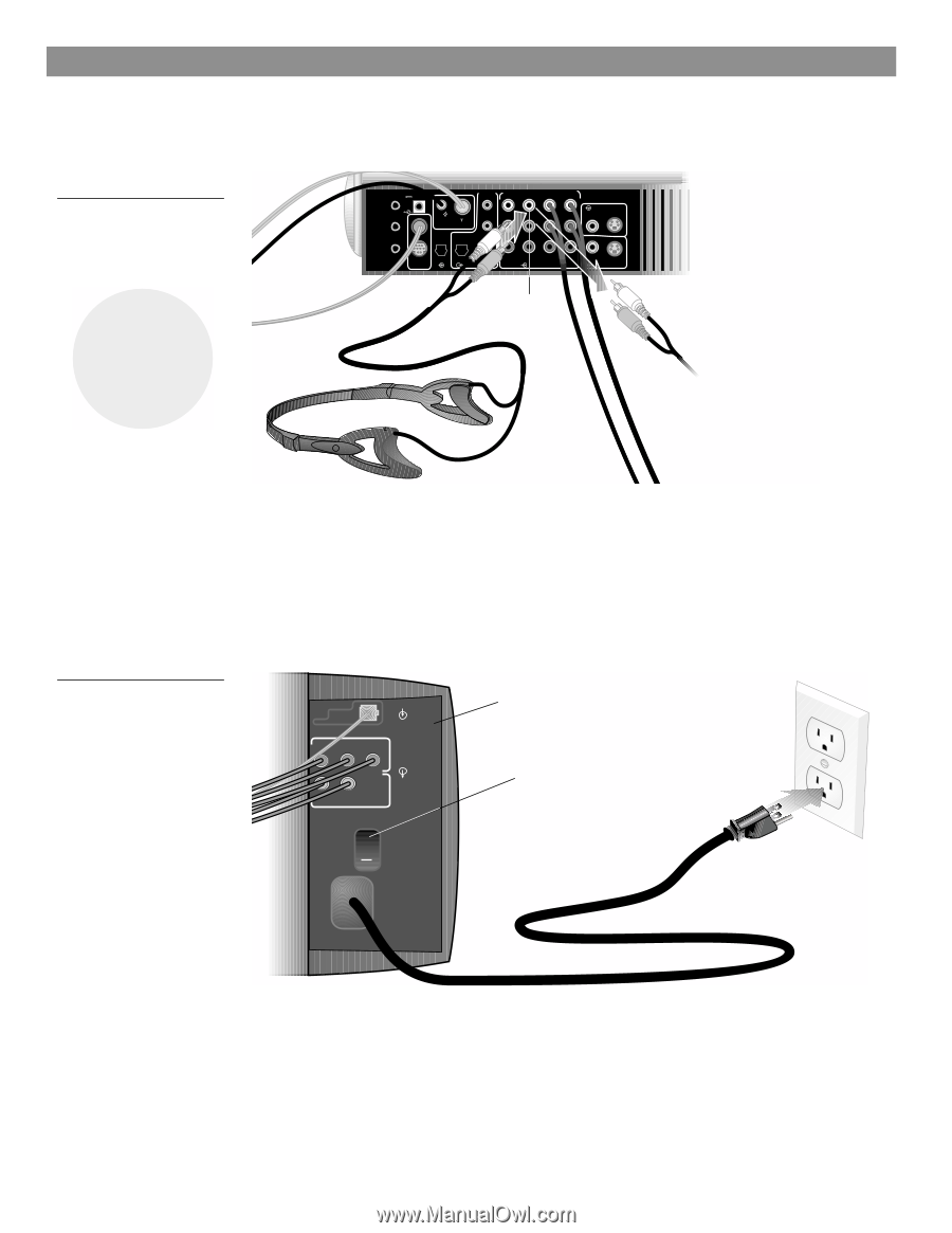
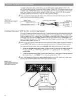
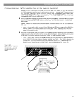
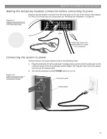
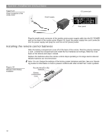
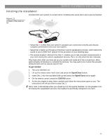
System Installation Instructions Making the temporary headset connection before connecting to power Plug the special headset connector into the AUX jacks on the rear of the media center (Figure 17). This is for temporary use during steps for "Finishing the installation" on page 21. Figure 17 Headset connection for use in the final setup steps TV SENSOR IR EMITTER SERIAL DATA 33V DC POWER 1.1A RECORD TAPE AUX VCR TV AM L L L L L FM 75 ANTENNA 1 OPTICAL OPTICAL R RR R R R VIDEO INPUTS COMPOSITE S-VIDEO 2 SPEAKER ZONES INPUT OUTPUT DIGITAL AUDIO OUTPUTS DIGITAL DIGITAL DIGITAL AUDIO INPUTS DIGITAL COMPOSITE S-VIDEO VIDEO OUTPUTS 5 AUX Temporarily remove the cable/satellite box cable if it is connected Connecting the system to power Connect the two AC power (mains) cords in the following order: 1. Plug the small end of the Acoustimass® module power cord into the AC power jack on the connector panel of the Acoustimass module (Figure 18). Plug the other end of the power cord into an AC (mains) outlet. 2. Turn the Acoustimass module POWER switch to on ( l ). Figure 18 Power connection of the Acoustimass module Connector panel AUDIO INPUT L C R FRONT Power switch OUTPUTS TO CUBE SPEAKERS SURROUND L R POWER 100-120/200-240V AC 50/60 Hz 350W MAX. 19 AM259777_02_V.pdf • April 23, 2002
-
 1
1 -
2
-
3
-
4
-
5
-
6
-
7
-
8
-
9
-
10
-
11
-
12
-
13
-
 14
14 -
 15
15 -
 16
16 -
 17
17 -
 18
18 -
 19
19 -
 20
20 -
 21
21 -
 22
22 -
 23
23 -
 24
24 -
25
-
26
-
27
-
28
-
29
-
30
-
31
-
32
 |
 |