Brother International KE-436C Inner Clamping Device Instruction Manual - Engli - Page 9
Replacing the work clamp crank and work clamp plate holder
 |
View all Brother International KE-436C manuals
Add to My Manuals
Save this manual to your list of manuals |
Page 9 highlights
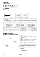
2 2. INSTALLATION 5 R(10 L(11 7 5. Attach the positioning plate R (10) and the positioning plate L (11) to the outer work clamp (7). 2961Q 2-1-1 2-1-1. Replacing the work clamp crank and work clamp plate holder 条件 2、条件 3 For Condition 2 and Condition 3, the work clamp crank and work clamp plate holder must be replaced. 2639Q 図 1 / Fig.1 2640Q 1. 締ねじ(1 2 3 2. 締ねじ(4 5 4 3 6 2 7 (図 1 6 8 1 1. Remove the screw (1), and remove the work clamp crank (3) from the work clamp crank holder (2). 2. Remove the screw (4) to replace the work clamp plate holder (5) with the optional one, and install it with the screw (4). 3. Insert the work clamp crank (6) into the work clamp crank holder (2). Then while pulling out the reversal cylinder piston rod (7) (Fig. 1), set the work clamp crank (6) so that it faces as shown in the illustration, align its groove with the washer (8), and then tighten the screw (1) to secure it. KE-435C,436C 6
-
 1
1 -
2
-
3
-
 4
4 -
 5
5 -
 6
6 -
 7
7 -
 8
8 -
 9
9 -
 10
10 -
 11
11 -
 12
12 -
 13
13 -
 14
14 -
15
-
16
-
17
-
18
-
19
-
20
 |
 |
