Brother International LK3-B434E MKII Instruction Manual - English - Page 6

Contents, Setting The Work Clamp Mode

Page 6 highlights

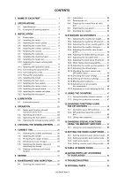
CONTENTS 1. NAME OF EACH PART 01 2. SPECIFICATIONS 02 2-1. Specifications 2 2-2. Examples of sewing patterns 3 3. INSTALLATION 04 3-1. Power table 4 3-2. Installing the motor 5 3-3. Installing the motor pulley 5 3-4. Installing the control box 6 3-5. Installing the rubber cushions 7 3-6. Installing the oil pan 7 3-7. Installing the cushions 7 3-8. Installing the machine head 8 3-9. Installing the head rest 8 3-10. Installing the liquid cooling tank, optional 8 3-11. Installing the operation panel 9 3-12. Connecting the ground wire 9 3-13. Connecting the cords 10 3-14. Piping (for pneumatic 12 3-15. Installing the V-belt 14 3-16. Installing the belt cover 15 3-17. Installing the foot switch 15 3-18. Installing the motor cover 16 3-19. Installing the spool stand 16 3-20. Installing the needle sub plate 17 3-21. Installing the eye guard 18 4. LUBRICATION 19 4-1. Lubrication points 19 5. OPERATION 20 5-1. Name and function of each operation panel item 20 5-2. Operating procedure 22 5-3. Operating the foot switch 23 5-4. Operating the emergency stop switch ... 24 6. CHECKING THE SEWING PATTERN ....... 25 7. CORRECT USE 26 7-1. Selecting the needle and thread ........ 26 7-2. Installing the needle 26 7-3. Threading the upper thread 26 7-4. Winding the lower thread 27 7-5. Replacing the bobbin case and threading the thread 28 7-6. Sewing conditions and thread tension 28 8. SEWING 31 9. MAINTENANCE AND INSPECTION ....... 32 9-1. Cleaning the rotary hook 32 9-2. Lubrication 33 9-3. Draining the oil 34 9-4. Cleaning the control box air inlet port 34 9-5. Cleaning the eye guard 34 9-6. Checking the needle 34 10.STANDARD ADJUSTMENTS 35 10-1. Adjusting the needle bar height ......... 35 10-2. Adjusting the needle bar lift amount ..... 35 10-3. Adjusting the driver needle guard ..... 36 10-4. Adjusting the needle clearance .......... 36 10-5. Adjusting the shuttle race thread guide 36 10-6. Adjusting the thread take-up amount .... 37 10-7. Adjusting the movable knife 37 10-8. Adjusting the work clamp lift amount ... 40 10-9. Work clamp interchangeability 41 10-10.Adjusting the needle up stop position ... 41 10-11.Adjusting the thread wiper 42 10-12.Checking the input sensor and DIP switch input 43 10-13.Checking the input voltage 44 10-14.Clearing all memory settings 44 10-15.Moving stitch patterns 45 10-16.Adjustment of air pressure (for pneumatic 46 10-17.Adjustment of inner clamping device .... 46 11.USING THE COUNTERS 47 11-1. Using the bobbin thread counter ....... 47 11-2. Using the production counter 47 12.CHANGING FUNCTIONS USING THE DIP SWITCHES 48 12-1. Operation panel DIP switches 48 12-2. DIP switches inside the control box 49 12-3. Using user programs 50 13.CHANGING SPECIAL FUNCTIONS USING THE MEMORY SWITCHES ........ 52 13-1. Using the cycle sewing function ........ 55 14.SETTING THE WORK CLAMP MODE .... 57 14-1. Setting solenoid work clamp mode ... 57 14-2. Setting pneumatic work clamp mode .... 57 14-3. Light work clamp 58 14-4. Setting reverse work clamp mode ..... 59 15.TABLE OF ERROR CODES 60 16.GAUGE PARTS LIST ACCORDING TO SUBCLASSES 62 17.TROUBLESHOOTING 65 18.OPTIONAL PARTS 68 LK3-B434E Mark II

  • 1
  • 2
  • 3
  • 4
  • 5
  • 6
  • 7
  • 8
  • 9
  • 10
  • 11
  • 12
  • 13
  • 14
  • 15
  • 16
  • 17
  • 18
  • 19
  • 20
  • 21
  • 22
  • 23
  • 24
  • 25
  • 26
  • 27
  • 28
  • 29
  • 30
  • 31
  • 32
  • 33
  • 34
  • 35
  • 36
  • 37
  • 38
  • 39
  • 40
  • 41
  • 42
  • 43
  • 44
  • 45
  • 46
  • 47
  • 48
  • 49
  • 50
  • 51
  • 52
  • 53
  • 54
  • 55
  • 56
  • 57
  • 58
  • 59
  • 60
  • 61
  • 62
  • 63
  • 64
  • 65
  • 66
  • 67
  • 68
  • 69
  • 70
  • 71
  • 72
  • 73
  • 74
  • 75

LK3-B434E Mark II
CONTENTS
1.
NAME OF EACH PART
...............................
0
1
2. SPECIFICATIONS
.........................................
0
2
2-1.
Specifications
.......................................
2
2-2.
Examples of sewing patterns
.............
3
3. INSTALLATION
.............................................
0
4
3-1.
Power table
...........................................
4
3-2.
Installing the motor
.............................
5
3-3.
Installing the motor pulley
..................
5
3-4.
Installing the control box
....................
6
3-5.
Installing the rubber cushions
............
7
3-6.
Installing the oil pan
............................
7
3-7.
Installing the cushions
.........................
7
3-8.
Installing the machine head
...............
8
3-9.
Installing the head rest
........................
8
3-10.
Installing the liquid cooling tank,
optional
.................................................
8
3-11.
Installing the operation panel
.............
9
3-12.
Connecting the ground wire
...............
9
3-13.
Connecting the cords
...........................
10
3-14.
Piping (for pneumatic)
.........................
12
3-15.
Installing the V-belt
..............................
14
3-16.
Installing the belt cover
.......................
15
3-17.
Installing the foot switch
.....................
15
3-18.
Installing the motor cover
...................
16
3-19.
Installing the spool stand
....................
16
3-20.
Installing the needle sub plate
...........
17
3-21.
Installing the eye guard
......................
18
4. LUBRICATION
...............................................
19
4-1.
Lubrication points
................................
19
5. OPERATION
..................................................
20
5-1.
Name and function of each
operation panel item
...........................
20
5-2.
Operating procedure
............................
22
5-3.
Operating the foot switch
...................
23
5-4.
Operating the emergency stop switch ...
24
6.
CHECKING THE SEWING PATTERN
.......
25
7.
CORRECT USE
.........................................
26
7-1.
Selecting the needle and thread
........
26
7-2.
Installing the needle
............................
26
7-3.
Threading the upper thread
................
26
7-4.
Winding the lower thread
...................
27
7-5.
Replacing the bobbin case and
threading the thread
............................
28
7-6.
Sewing conditions and thread
tension
...................................................
28
8. SEWING
...................................................
31
9.
MAINTENANCE AND INSPECTION
.......
32
9-1.
Cleaning the rotary hook
....................
32
9-2.
Lubrication
............................................
33
9-3.
Draining the oil
.....................................
34
9-4.
Cleaning the control box air inlet
port
........................................................
34
9-5.
Cleaning the eye guard
.......................
34
9-6.
Checking the needle
............................
34
10.STANDARD ADJUSTMENTS
.................
35
10-1.
Adjusting the needle bar height
.........
35
10-2.
Adjusting the needle bar lift amount
.....
35
10-3.
Adjusting the driver needle guard
.....
36
10-4.
Adjusting the needle clearance
..........
36
10-5.
Adjusting the shuttle race thread
guide
......................................................
36
10-6.
Adjusting the thread take-up amount
....
37
10-7.
Adjusting the movable knife
...............
37
10-8.
Adjusting the work clamp lift amount ...
40
10-9.
Work clamp interchangeability
...........
41
10-10.
Adjusting the needle up stop position ...
41
10-11.Adjusting the thread wiper
.................
42
10-12.Checking the input sensor and
DIP switch input
...................................
43
10-13.Checking the input voltage
.................
44
10-14.Clearing all memory settings
.............
44
10-15.Moving stitch patterns
.........................
45
10-16.Adjustment of air pressure
(for pneumatic)
.....................................
46
10-17.
Adjustment of inner clamping device
....
46
11.USING THE COUNTERS
.........................
47
11-1.
Using the bobbin thread counter
.......
47
11-2.
Using the production counter
............
47
12.CHANGING FUNCTIONS USING
THE DIP SWITCHES
................................
48
12-1.
Operation panel DIP switches
............
48
12-2.
DIP switches inside the control
box
.........................................................
49
12-3.
Using user programs
...........................
50
13.CHANGING SPECIAL FUNCTIONS
USING THE MEMORY SWITCHES
........
52
13-1.
Using the cycle sewing function
........
55
14.SETTING THE WORK CLAMP MODE
....
57
14-1.
Setting solenoid work clamp mode ... 57
14-2.
Setting pneumatic work clamp mode
....
57
14-3.
Light work clamp
.................................
58
14-4.
Setting reverse work clamp mode
.....
59
15.TABLE OF ERROR CODES
......................
60
16.GAUGE PARTS LIST ACCORDING
TO SUBCLASSES
....................................
62
17.TROUBLESHOOTING
.................................
65
18.OPTIONAL PARTS
.......................................
68