Brother International PR-1000 PE-DESIGN NEXT CW Instruction Manual PRCW1 - Page 9
Color order, Design Property, Cutting, Running Stitch, Machine Type, Design Design, Settings
 |
View all Brother International PR-1000 manuals
Add to My Manuals
Save this manual to your list of manuals |
Page 9 highlights
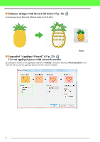
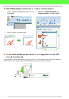
6 Design Page The cutting lines appear as gray dotted lines in the Design Page, regardless of whether the "Solid View", "Stitch View" or "Realistic View" is selected. 7 "Sewing Attributes" In the "Sewing Attributes" pane, detailed cutting settings can be specified for the cutwork functions. 8 Previewing cutting lines In the Stitch Simulator pane, the cutwork needles are displayed in four different shades of gray. In a stitch simulation, the cutting lines appear as short gray lines, indicating the needle drop points for making the cuts. While being edited In a stitch simulation 9 Checking "Design Property" When "Cutting" has been assigned to a line from the "Line Sew Type" selector, "Design Property" screen appears as shown below. Getting Started b Memo: "Color order" can be also viewed in the "Design Property" screen in the Design Database. a Note: • Designs containing the line sew type "Cutting" are saved as cutwork patterns. • Cutwork patterns can be edited only with a version of PE-DESIGN NEXT + CW that has the cutwork functions enabled. • Created cutwork patterns can be used only with embroidery machines upgraded for cutwork. • With PE-DESIGN NEXT + CW, the line sew type "Cutting" changes to "Running Stitch" in the following situations. • When the "Machine Type" setting (on the "Design Page" tab of the "Design Settings" dialog box) is changed from a multi-needle embroidery machine to a single-needle embroidery machine • When a cutwork pattern is imported while "Machine Type" (on the "Design Page" tab) is set to a singleneedle embroidery machine • Cutwork pattern cannot be transferred to a machine by using an embroidery card or the Link function. • Cutwork pattern cannot be created in Design Center. To set the line sew type to "Cutting", use Layout & Editing. The setting cannot be specified in Design Center. 7
-
 1
1 -
2
-
3
-
 4
4 -
 5
5 -
 6
6 -
 7
7 -
 8
8 -
 9
9 -
 10
10 -
 11
11 -
 12
12 -
 13
13 -
 14
14 -
15
-
16
-
17
-
18
-
19
-
20
-
21
-
22
-
23
-
24
-
25
-
26
-
27
-
28
-
29
 |
 |
