Cisco 3725 Hardware Installation Guide - Page 106
Bit 10, Address <net> <host>, boot system
 |
UPC - 746320810911
View all Cisco 3725 manuals
Add to My Manuals
Save this manual to your list of manuals |
Page 106 highlights
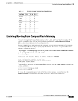
Configuring the Boot Field Appendix C Configuration Register The boot field specifies a number in binary form. If you set the boot field value to 0, you must have console port access to boot the operating system manually. See the boot command in the "ROM Monitor Command Descriptions" section on page B-3. If you set the boot field to a value of 2 to F, and a valid boot system command is stored in the configuration file, the router software processes each boot command in sequence until the process is successful or the end of the list is reached. If no boot commands are in the configuration file, the router attempts to boot the first file in CompactFlash memory. In the following example, the configuration register is set to boot the router automatically from CompactFlash memory and to ignore Break at the next reboot of the router: Router# configure terminal Enter configuration commands, one per line. Edit with DELETE, CTRL/W, and CTRL/U; end with CTRL/Z config-register 0x102 Ctrl-z Router# Note A boot system command in the router configuration in NVRAM overrides booting from CompactFlash memory. Bit 8 controls the console Break key. Setting bit 8 (the factory default) causes the processor to ignore the console Break key. Clearing bit 8 causes the processor to interpret Break as a command to force the router into the bootstrap monitor, halting normal operation. Break can always be sent in the first 60 seconds while the router is rebooting, regardless of the configuration settings. Bit 9 controls the system boot. Clearing bit 9 (the factory default) causes the system to boot from CompactFlash memory. Clearing bit 9 causes the system to use the secondary bootstrap. This bit is typically not used. Bit 10 controls the host portion of the IP broadcast address. Setting bit 10 causes the processor to use all zeros; clearing bit 10 (the factory default) causes the processor to use all ones. Bit 10 interacts with bit 14, which controls the network and subnet portions of the broadcast address. Table C-3 shows the combined effect of bits 10 and 14. Table C-3 Configuration Register Settings for Broadcast Address Destination Bit 10 Bit 14 Address ( ) Off Off On Off On On Off On Bit 13 determines how the router responds to a bootload failure. Setting bit 13 causes the router to load operating software from ROM after six unsuccessful attempts to load a boot file. Clearing bit 13 causes the router to continue indefinitely to attempt loading a boot file. By factory default, bit 13 is set to 0. Bits 5, 11, and 12 of the configuration register determine the data rate of the console terminal. Table C-4 shows the bit settings for the eight available rates. (The default data rate is 9600 bps.) Cisco 3700 Series Routers Hardware Installation Guide C-4 OL-2180-08
-
 1
1 -
2
-
3
-
4
-
5
-
6
-
7
-
8
-
9
-
10
-
11
-
12
-
13
-
14
-
15
-
16
-
17
-
18
-
19
-
20
-
21
-
22
-
23
-
24
-
25
-
26
-
27
-
28
-
29
-
30
-
31
-
32
-
33
-
34
-
35
-
36
-
37
-
38
-
39
-
40
-
41
-
42
-
43
-
44
-
45
-
46
-
47
-
48
-
49
-
50
-
51
-
52
-
53
-
54
-
55
-
56
-
57
-
58
-
59
-
60
-
61
-
62
-
63
-
64
-
65
-
66
-
67
-
68
-
69
-
70
-
71
-
72
-
73
-
74
-
75
-
76
-
77
-
78
-
79
-
80
-
81
-
82
-
83
-
84
-
85
-
86
-
87
-
88
-
89
-
90
-
91
-
92
-
93
-
94
-
95
-
96
-
97
-
98
-
99
-
100
-
 101
101 -
 102
102 -
 103
103 -
 104
104 -
 105
105 -
 106
106 -
 107
107 -
 108
108 -
 109
109 -
 110
110 -
 111
111 -
112
-
113
-
114
 |
 |
