Cisco 3725 Hardware Installation Guide - Page 65
Terminal Block Connections for Negative Polarity DC Input Power in Cisco 3745 Router
 |
UPC - 746320810911
View all Cisco 3725 manuals
Add to My Manuals
Save this manual to your list of manuals |
Page 65 highlights
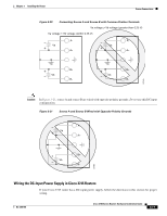
Chapter 3 Installing the Router Power Connections Warning When stranded wiring is required, use approved wiring terminations, such as closed-loop or spade-type with upturned lugs. These terminations should be the appropriate size for the wires and should clamp both the insulation and conductor. Statement 1002 Step 4 Remove the plastic cover from the terminal block. Save it for reinstallation after you finish wiring. Step 5 Connect the DC power input wires to the terminal block as shown in Figure 3-22 or Figure 3-23. Warning The illustration shows the DC power supply terminal block. Wire the DC power supply as illustrated. The proper wiring sequence is ground to ground, positive to positive, and negative to negative. The ground wire should always be connected first and disconnected last. Statement 239 Caution Do not overtorque the terminal block screws. The recommended torque is 8.0 ± 0.5 in-lb (0.9 ± 0.05 N-m). Figure 3-22 Terminal Block Connections for Negative Polarity DC Input Power in Cisco 3745 Router Negative polarity input 0V (return) Safety ground 88658 Figure 3-23 Terminal Block Connections for Positive Polarity DC Input Power in Cisco 3745 Router 0V (return) Positive polarity input Safety ground 88657 Step 6 Install the plastic cover over the terminal block. Warning The safety cover is an integral part of the product. Do not operate the unit without the safety cover installed. Operating the unit without the cover in place will invalidate the safety approvals and pose a risk of fire and electrical hazards. Statement 117 Step 7 Secure the wires using cable ties. OL-2180-08 Cisco 3700 Series Routers Hardware Installation Guide 3-19
-
 1
1 -
2
-
3
-
4
-
5
-
6
-
7
-
8
-
9
-
10
-
11
-
12
-
13
-
14
-
15
-
16
-
17
-
18
-
19
-
20
-
21
-
22
-
23
-
24
-
25
-
26
-
27
-
28
-
29
-
30
-
31
-
32
-
33
-
34
-
35
-
36
-
37
-
38
-
39
-
40
-
41
-
42
-
43
-
44
-
45
-
46
-
47
-
48
-
49
-
50
-
51
-
52
-
53
-
54
-
55
-
56
-
57
-
58
-
59
-
 60
60 -
 61
61 -
 62
62 -
 63
63 -
 64
64 -
 65
65 -
 66
66 -
 67
67 -
 68
68 -
 69
69 -
 70
70 -
71
-
72
-
73
-
74
-
75
-
76
-
77
-
78
-
79
-
80
-
81
-
82
-
83
-
84
-
85
-
86
-
87
-
88
-
89
-
90
-
91
-
92
-
93
-
94
-
95
-
96
-
97
-
98
-
99
-
100
-
101
-
102
-
103
-
104
-
105
-
106
-
107
-
108
-
109
-
110
-
111
-
112
-
113
-
114
 |
 |
