Cisco 3725 Hardware Installation Guide - Page 73
Power-Up Procedure, Cisco 3745 LED Indicators
 |
UPC - 746320810911
View all Cisco 3725 manuals
Add to My Manuals
Save this manual to your list of manuals |
Page 73 highlights
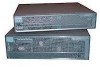
Chapter 3 Installing the Router Powering Up the Router Cisco 3745 LED Indicators The following indicator LEDs on the front of the chassis provide power, activity, and status information: • SYS-System status: - Blinking green during bootup-System is booting - Continuous green-System booted and OK - Blinking green continuing after bootup-System is in ROM monitor mode - Amber-System malfunction • ACT-Activity: - Blinking or continuous green during system activity, such as interrupts and packet transfers • SYS PS1 or SYS PS2-Chassis power supply number 1 or number 2 status: - Off-Powered off, not installed, or faulty - Continuous green-Installed and operating - Amber-Installed and powered off or faulty • -48V PS1 or -48V PS2-IP power module number 1 or number 2 status: - Off-Faulty or not installed - Continuous green-Installed and operating - Amber-Installed and powered off or faulty Power-Up Procedure To power up your Cisco router and verify that it goes through its initialization and self-test, follow this procedure. When the procedure is finished, the Cisco router is ready to configure. If you encounter problems when you power up the router, see Appendix A, "Troubleshooting." For information about the ROM monitor and the bootstrap program, see Appendix B, "Using the ROM Monitor." For information about the configuration register, see Appendix C, "Configuration Register." Note To view the boot sequence through a terminal session, you must have a console connection to the Cisco router before it powers up. Step 1 Step 2 Make sure that your PC is powered up and connected as described in the "Checklist for Power Up" section on page 3-26. Move the power switch to the ON position. Note Cisco 3745 routers may have one or two chassis power supplies. A router may operate with either power supply or with both power supplies in use. Two power supplies provide redundancy. OL-2180-08 Cisco 3700 Series Routers Hardware Installation Guide 3-27
-
 1
1 -
2
-
3
-
4
-
5
-
6
-
7
-
8
-
9
-
10
-
11
-
12
-
13
-
14
-
15
-
16
-
17
-
18
-
19
-
20
-
21
-
22
-
23
-
24
-
25
-
26
-
27
-
28
-
29
-
30
-
31
-
32
-
33
-
34
-
35
-
36
-
37
-
38
-
39
-
40
-
41
-
42
-
43
-
44
-
45
-
46
-
47
-
48
-
49
-
50
-
51
-
52
-
53
-
54
-
55
-
56
-
57
-
58
-
59
-
60
-
61
-
62
-
63
-
64
-
65
-
66
-
67
-
 68
68 -
 69
69 -
 70
70 -
 71
71 -
 72
72 -
 73
73 -
 74
74 -
 75
75 -
 76
76 -
 77
77 -
 78
78 -
79
-
80
-
81
-
82
-
83
-
84
-
85
-
86
-
87
-
88
-
89
-
90
-
91
-
92
-
93
-
94
-
95
-
96
-
97
-
98
-
99
-
100
-
101
-
102
-
103
-
104
-
105
-
106
-
107
-
108
-
109
-
110
-
111
-
112
-
113
-
114
 |
 |
