Cisco 3725 Hardware Installation Guide - Page 68
Connecting to a Console Terminal or Modem, Connecting to the Console Port
 |
UPC - 746320810911
View all Cisco 3725 manuals
Add to My Manuals
Save this manual to your list of manuals |
Page 68 highlights
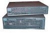
Connecting to a Console Terminal or Modem Chapter 3 Installing the Router • Install cable ties in accordance with site requirements. For cable pinouts, see the online document Cisco Modular Access Router Cable Specifications. Connecting to a Console Terminal or Modem Your router has asynchronous serial console and auxiliary ports. These ports provide administrative access to your router either locally (with a console terminal or PC) or remotely (with a modem). Cisco provides the following cables and adapters for connecting your router to a console terminal, PC, or modem: • One console adapter cable (RJ-45-to-DB-9, blue) • One modem adapter cable (RJ-45-to-DB-25, black) This section describes how to connect a console terminal or PC to the console port, and how to connect a modem to the auxiliary port. Note For information on identifying rollover cables, see the "Identifying a Rollover Cable" section on page 3-25. Connecting to the Console Port To connect a console terminal or a PC running terminal emulation software to the console port on the router, perform the following steps: Step 1 Use the blue RJ-45-to-DB-9 console adapter cable to connect the router to a terminal. (See Figure 3-24 and Figure 3-25.) For information about cable pinouts, see the online publication Cisco Modular Access Router Cable Specifications, available online and on the Documentation CD-ROM. Note On Cisco routers, the console port is color-coded blue. Step 2 Configure your terminal or terminal emulation software for 9600 baud (default), 8 data bits, no parity, and 2 stop bits. Note Because hardware flow control is not possible on the console port, we do not recommend that modems be connected to the console port. Modems should always be connected to the auxiliary port. 3-22 Cisco 3700 Series Routers Hardware Installation Guide OL-2180-08
-
 1
1 -
2
-
3
-
4
-
5
-
6
-
7
-
8
-
9
-
10
-
11
-
12
-
13
-
14
-
15
-
16
-
17
-
18
-
19
-
20
-
21
-
22
-
23
-
24
-
25
-
26
-
27
-
28
-
29
-
30
-
31
-
32
-
33
-
34
-
35
-
36
-
37
-
38
-
39
-
40
-
41
-
42
-
43
-
44
-
45
-
46
-
47
-
48
-
49
-
50
-
51
-
52
-
53
-
54
-
55
-
56
-
57
-
58
-
59
-
60
-
61
-
62
-
 63
63 -
 64
64 -
 65
65 -
 66
66 -
 67
67 -
 68
68 -
 69
69 -
 70
70 -
 71
71 -
 72
72 -
 73
73 -
74
-
75
-
76
-
77
-
78
-
79
-
80
-
81
-
82
-
83
-
84
-
85
-
86
-
87
-
88
-
89
-
90
-
91
-
92
-
93
-
94
-
95
-
96
-
97
-
98
-
99
-
100
-
101
-
102
-
103
-
104
-
105
-
106
-
107
-
108
-
109
-
110
-
111
-
112
-
113
-
114
 |
 |
