Cisco 3725 Hardware Installation Guide - Page 64
DC Wiring Requirements for Cisco 3745 Routers, Wiring Procedure for DC Input, Installed Power Supply
 |
UPC - 746320810911
View all Cisco 3725 manuals
Add to My Manuals
Save this manual to your list of manuals |
Page 64 highlights
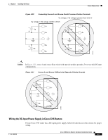
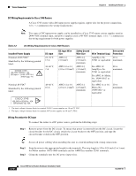
Power Connections Chapter 3 Installing the Router DC Wiring Requirements for Cisco 3745 Routers A Cisco 3745 router with a DC-input power supply requires copper wire for the power connections. Table 3-2 summarizes the wiring requirements. Note Two types of DC input power supply can be installed in a Cisco 3745 router: power supplies rated at 24/48 VDC nominal input, and power supplies rated at 48 VDC nominal input. Table 3-2 summarizes the wiring requirement for both power supplies. Table 3-2 DC Wiring Requirements for Cisco 3745 Routers Installed Power Supply Nominal 24/48 VDC1 Identified by the following printed label: ~ CISCO 3745 100-240V 50/60Hz 10A OR Input +/- 24-36 V 15 A ! 36-60 V 7 A DC Input 24-36 V, 15 A 36-60 V, 7A Nominal 48 VDC2 Identified by the following printed label: 48-60 V, 10 A DC Input Wire Size Safety Ground Overcurrent Wire Size Wire Terminal (Lug) Protection AWG 12 (3.0 mm2) AWG 12 (3.0 mm2), minimum Amp/Tyco No. 20 A 52961 or equivalent maximum AWG 12 or 14 AWG 12 (3.0 or 2.0 mm2) (3.0 mm2), minimum For AWG 12: 20 A Amp/Tyco No. maximum 52961 or equivalent For AWG 14: Molex No. 19099-0017 or equivalent AWG 14 or 16 AWG 14 (2.0 or 1.2 mm2) (2.0 mm2), minimum For AWG 14 or 16: Molex No. 19099-0017 or equivalent 20 A maximum ! CISCO 3745 ~ 100-240V 50/60Hz, 10A OR 48-60V , 10A 1. The input voltage tolerance limits for nominal 24/48-V power supplies are 18 and 72 VDC. 2. The input voltage tolerance limits for nominal 48-V power supplies are 38 and 72 VDC. Wiring Procedure for DC Input To connect the router to a DC power source, perform the following steps: Step 1 Remove power from the DC circuit. To ensure that power is removed from the DC circuit, locate the circuit breaker for the DC circuit, switch the circuit breaker to the OFF position, and tape the circuit-breaker switch in the OFF position. Tip Secure all power cabling when installing this unit to avoid disturbing field-wiring connections. Step 2 Step 3 Strip the wires to the appropriate length for the terminals. The strip length is 1/8 to 3/16 inch (3 to 5 mm) for Molex number 19073-0009 terminals and for AMP/Tyco number 52961 terminals. Crimp the terminals onto the DC power input wires. 3-18 Cisco 3700 Series Routers Hardware Installation Guide OL-2180-08
-
 1
1 -
2
-
3
-
4
-
5
-
6
-
7
-
8
-
9
-
10
-
11
-
12
-
13
-
14
-
15
-
16
-
17
-
18
-
19
-
20
-
21
-
22
-
23
-
24
-
25
-
26
-
27
-
28
-
29
-
30
-
31
-
32
-
33
-
34
-
35
-
36
-
37
-
38
-
39
-
40
-
41
-
42
-
43
-
44
-
45
-
46
-
47
-
48
-
49
-
50
-
51
-
52
-
53
-
54
-
55
-
56
-
57
-
58
-
 59
59 -
 60
60 -
 61
61 -
 62
62 -
 63
63 -
 64
64 -
 65
65 -
 66
66 -
 67
67 -
 68
68 -
 69
69 -
70
-
71
-
72
-
73
-
74
-
75
-
76
-
77
-
78
-
79
-
80
-
81
-
82
-
83
-
84
-
85
-
86
-
87
-
88
-
89
-
90
-
91
-
92
-
93
-
94
-
95
-
96
-
97
-
98
-
99
-
100
-
101
-
102
-
103
-
104
-
105
-
106
-
107
-
108
-
109
-
110
-
111
-
112
-
113
-
114
 |
 |
