Cisco AIR-BR1310G-A-K9 Hardware Installation Guide - Page 100
Overview, Signals and Pinouts - air - a -
 |
UPC - 746320927565
View all Cisco AIR-BR1310G-A-K9 manuals
Add to My Manuals
Save this manual to your list of manuals |
Page 100 highlights
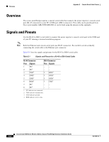
Overview Appendix E Console Serial Cable Pinouts Overview The access point/bridge requires a special serial cable that connects the power injector's console serial port (RJ-45 connector) to your PC's COM port (DB-9 connector). This cable can be purchased from Cisco (part number AIR-CONCAB1200) or can be built using the pinouts in this appendix. Signals and Pinouts Use the RJ-45 to DB-9 serial cable to connect the power injector's console serial port to the COM port of your PC running a terminal emulation program. Note Both the Ethernet and console serial ports use RJ-45 connectors. Be careful to avoid accidently connecting the serial cable to the Ethernet port connector. Table E-1 lists the signals and pinouts for the RJ-45 to DB-9 serial cable. Table E-1 Signals and Pinouts for a RJ-45 to DB-9 Serial Cable RJ-45 Connector DB-9 Connector Pins Signals 1 NC1 2 NC1 3 TXD2 4 GND3 5 GND3 6 RXD4 7 NC1 8 NC1 Pins Signals -- -- 2 RXD4 5 GND3 5 GND3 3 TXD2 -- -- 1. NC indicates not connected. 2. TXD indicates transmit data. 3. GND indicates ground. 4. RXD indicates receive data. Cisco Aironet 1300 Series Wireless Outdoor Access Point/Bridge Hardware Installation Guide E-2 OL-5048-06
-
 1
1 -
2
-
3
-
4
-
5
-
6
-
7
-
8
-
9
-
10
-
11
-
12
-
13
-
14
-
15
-
16
-
17
-
18
-
19
-
20
-
21
-
22
-
23
-
24
-
25
-
26
-
27
-
28
-
29
-
30
-
31
-
32
-
33
-
34
-
35
-
36
-
37
-
38
-
39
-
40
-
41
-
42
-
43
-
44
-
45
-
46
-
47
-
48
-
49
-
50
-
51
-
52
-
53
-
54
-
55
-
56
-
57
-
58
-
59
-
60
-
61
-
62
-
63
-
64
-
65
-
66
-
67
-
68
-
69
-
70
-
71
-
72
-
73
-
74
-
75
-
76
-
77
-
78
-
79
-
80
-
81
-
82
-
83
-
84
-
85
-
86
-
87
-
88
-
89
-
90
-
91
-
92
-
93
-
94
-
 95
95 -
 96
96 -
 97
97 -
 98
98 -
 99
99 -
 100
100 -
 101
101 -
 102
102 -
 103
103 -
 104
104 -
 105
105 -
106
-
107
-
108
-
109
-
110
-
111
-
112
-
113
-
114
-
115
-
116
-
117
-
118
 |
 |
