Cisco WS-C1912-A Hardware Installation Guide - Page 21
Hardware Features
 |
UPC - 746320021522
View all Cisco WS-C1912-A manuals
Add to My Manuals
Save this manual to your list of manuals |
Page 21 highlights
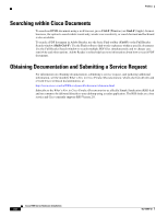
Chapter 1 Overview of the Router Hardware Features Figure 1-5 Back Panel of the Cisco 1941 and Cisco 1941W Router 17 18 19 20 21 22 EHWIC 1 DO NOT REMOVE DURING NETWORKING OPERATION CF 1 Cisco 1900 Series EHWIC 0 DO NOT REMOVE DURING CF 0 ISM/WLAN EN NETWORKING OPERATION AUX S L G E 0 / 0 EN CONSOLE GE 0/1 S L 1 USB 0 273452 16 15 14 13 12 11 10 9 8 7 6 5 4 3 2 1 USB ports-two USB 2.0 Type-A ports 1 (USB 0=Bottom) L (Link) 2 3 GE 0/1 4 S (Speed) 5 RJ-45 serial console port 6 EN (Enable RJ-45 console) USB serial port-USB 5-pin mini USB 7 Type-B 9 HWIC slot 0 (EHWIC, HWIC, WIC, or VWIC1)-single wide2 EN (Enable USB console) 8 10 ISM3 or WLAN 11 CF 0 12 CompactFlash 0 13 HWIC slot 1 (EHWIC, HWIC, or WIC)-double wide4 15 CompactFlash 1 14 CF 1 16 KensingtonTM security slot 17 On/Off switch 18 Input power connection 19 AUX port 20 S (Speed) 21 GE 0/0 22 L (Link) 1. VWIC support is for data only. 2. See Module Support on Cisco's Integrated Services Routers Generation 2 http://cisco.com/en/US/prod/collateral/routers/ps10538/aag_c07_563807.pdf for supported modules. 3. Internal Service Module (ISM). 4. The double-wide slot can accommodate a single wide EHWIC, HWIC, WIC, or VWIC (data only), on the left side of the slot. Hardware Features • Product Serial Number Location, page 1-6 • Built-In Interfaces, page 1-7 • Removable, Interchangeable, and Optional Modules, page 1-8 • Memory, page 1-9 • LED Indicators, page 1-10 OL-19084-02 Cisco 1900 Series Hardware Installation 1-5
-
 1
1 -
2
-
3
-
4
-
5
-
6
-
7
-
8
-
9
-
10
-
11
-
12
-
13
-
14
-
15
-
 16
16 -
 17
17 -
 18
18 -
 19
19 -
 20
20 -
 21
21 -
 22
22 -
 23
23 -
 24
24 -
 25
25 -
 26
26 -
27
-
28
-
29
-
30
-
31
-
32
-
33
-
34
-
35
-
36
-
37
-
38
-
39
-
40
-
41
-
42
-
43
-
44
-
45
-
46
-
47
-
48
-
49
-
50
-
51
-
52
-
53
-
54
-
55
-
56
-
57
-
58
-
59
-
60
-
61
-
62
-
63
-
64
-
65
-
66
-
67
-
68
-
69
-
70
-
71
-
72
-
73
-
74
-
75
-
76
-
77
-
78
-
79
-
80
-
81
-
82
-
83
-
84
-
85
-
86
-
87
-
88
-
89
-
90
-
91
-
92
-
93
-
94
-
95
-
96
-
97
-
98
-
99
-
100
-
101
-
102
 |
 |
