Cisco WS-C1912-A Hardware Installation Guide - Page 38
Power Supply Considerations, Site Environment, Site Configuration
 |
UPC - 746320021522
View all Cisco WS-C1912-A manuals
Add to My Manuals
Save this manual to your list of manuals |
Page 38 highlights
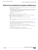
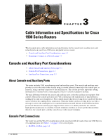
General Site Requirements Chapter 2 Preparing for Router Installation Power Supply Considerations Check the power at your site to ensure that you are receiving "clean" power (free of spikes and noise). Install a power conditioner if necessary. Warning The device is designed for connection to TN and IT power systems. Statement 1007 The AC power supply includes the following features: • Autoselects either 110 V or 220 V operation. • All units include a 6-foot (1.8-meter) electrical power cord. (A label near the power cord indicates the correct voltage, frequency, current draw, and power dissipation for the unit.) Site Environment The Cisco 1900 series router is designed for placement on a desktop, rack-mounted or wall mounted. The location of your router is an extremely important consideration for proper operation. Equipment placed too close together, inadequate ventilation, and inaccessible panels can cause malfunctions and shutdowns, and can also make maintenance difficult. Plan for access to both front and back panels of the router. When planning your site layout and equipment locations, remember the precautions described in the "Site Configuration" section on page 2-4 to help avoid equipment failures and reduce the possibility of environmentally caused shutdowns. If you are currently experiencing shutdowns or an unusually high number of errors with your existing equipment, these precautions may help you isolate the cause of the failures and prevent future problems. Site Configuration The following precautions will help you plan an acceptable operating environment for your router and will help you avoid environmentally caused equipment failures: • Make sure that the room where your router operates has adequate circulation. Electrical equipment generates heat. Without adequate circulation, ambient air temperature may not cool equipment to acceptable operating temperatures. See the "Chassis Airflow Diagram" section on page 4-3. • Always follow the ESD-prevention procedures described in the "Preventing Electrostatic Discharge Damage" section on page 2-3 to avoid damage to equipment. Damage from static discharge can cause immediate or intermittent equipment failure. • Make sure that the chassis cover and module back panels are secure. All empty interface card slots must have filler panels installed. The chassis is designed to allow cooling air to flow within it, through specially designed cooling slots. A chassis with uncovered openings creates air leaks, which may interrupt and reduce the flow of air across internal components. Cisco 1900 Series Hardware Installation 2-4 OL-19084-02
-
 1
1 -
2
-
3
-
4
-
5
-
6
-
7
-
8
-
9
-
10
-
11
-
12
-
13
-
14
-
15
-
16
-
17
-
18
-
19
-
20
-
21
-
22
-
23
-
24
-
25
-
26
-
27
-
28
-
29
-
30
-
31
-
32
-
 33
33 -
 34
34 -
 35
35 -
 36
36 -
 37
37 -
 38
38 -
 39
39 -
 40
40 -
 41
41 -
 42
42 -
 43
43 -
44
-
45
-
46
-
47
-
48
-
49
-
50
-
51
-
52
-
53
-
54
-
55
-
56
-
57
-
58
-
59
-
60
-
61
-
62
-
63
-
64
-
65
-
66
-
67
-
68
-
69
-
70
-
71
-
72
-
73
-
74
-
75
-
76
-
77
-
78
-
79
-
80
-
81
-
82
-
83
-
84
-
85
-
86
-
87
-
88
-
89
-
90
-
91
-
92
-
93
-
94
-
95
-
96
-
97
-
98
-
99
-
100
-
101
-
102
 |
 |
