Cisco WS-C1912-A Hardware Installation Guide - Page 58
Chassis Ground Connection on the Cisco 1905 and Cisco 1921 Routers, Step 1
 |
UPC - 746320021522
View all Cisco WS-C1912-A manuals
Add to My Manuals
Save this manual to your list of manuals |
Page 58 highlights
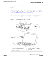
Installing the Chassis Ground Connection Chapter 4 Installing and Connecting the Router To install the ground connection for a Cisco 1900 series router, follow these steps. Procedure Step 1 Step 2 Step 3 Strip one end of the ground wire to expose approximately 0.75 in. (20 mm) of conductor. Crimp the 14 AWG green ground wire to a UL Listed/CSA certified ring terminal that is suitably sized for the number 6 ground screw provided on the rear panel of the router. The crimping tool should be one that is recommended by the ring lug terminal manufacturer. Attach the ring terminal to the chassis. The attachment points are shown in Figure 4-10 and Figure 4-11. Use a number 2 Phillips screwdriver and the screw supplied with the ground lug. Tighten the screw to a torque of 8 to 10 in-lb. (0.9 to 1.1 N-m). Figure 4-10 Chassis Ground Connection on the Cisco 1905 and Cisco 1921 Routers AUX S GE 0/1 L CONSOLE S GE 0/0 L BAUD POE RESET 48VDC 1.67A Cisco 1905 100-240 V~ 50-60 Hz 1A 253714 Figure 4-11 Chassis Ground Connection on the Cisco 1941 Router S G L E 0 / 0 EN EN 1 CONSOLE USB GE 0/1 0 251359 4-10 Cisco 1900 Series Hardware Installation OL-19084-02
-
 1
1 -
2
-
3
-
4
-
5
-
6
-
7
-
8
-
9
-
10
-
11
-
12
-
13
-
14
-
15
-
16
-
17
-
18
-
19
-
20
-
21
-
22
-
23
-
24
-
25
-
26
-
27
-
28
-
29
-
30
-
31
-
32
-
33
-
34
-
35
-
36
-
37
-
38
-
39
-
40
-
41
-
42
-
43
-
44
-
45
-
46
-
47
-
48
-
49
-
50
-
51
-
52
-
 53
53 -
 54
54 -
 55
55 -
 56
56 -
 57
57 -
 58
58 -
 59
59 -
 60
60 -
 61
61 -
 62
62 -
 63
63 -
64
-
65
-
66
-
67
-
68
-
69
-
70
-
71
-
72
-
73
-
74
-
75
-
76
-
77
-
78
-
79
-
80
-
81
-
82
-
83
-
84
-
85
-
86
-
87
-
88
-
89
-
90
-
91
-
92
-
93
-
94
-
95
-
96
-
97
-
98
-
99
-
100
-
101
-
102
 |
 |
