D-Link DXS-3600-EM-STACK Hardware Installation Guide - Page 17
Installing a DC Power Module
 |
View all D-Link DXS-3600-EM-STACK manuals
Add to My Manuals
Save this manual to your list of manuals |
Page 17 highlights
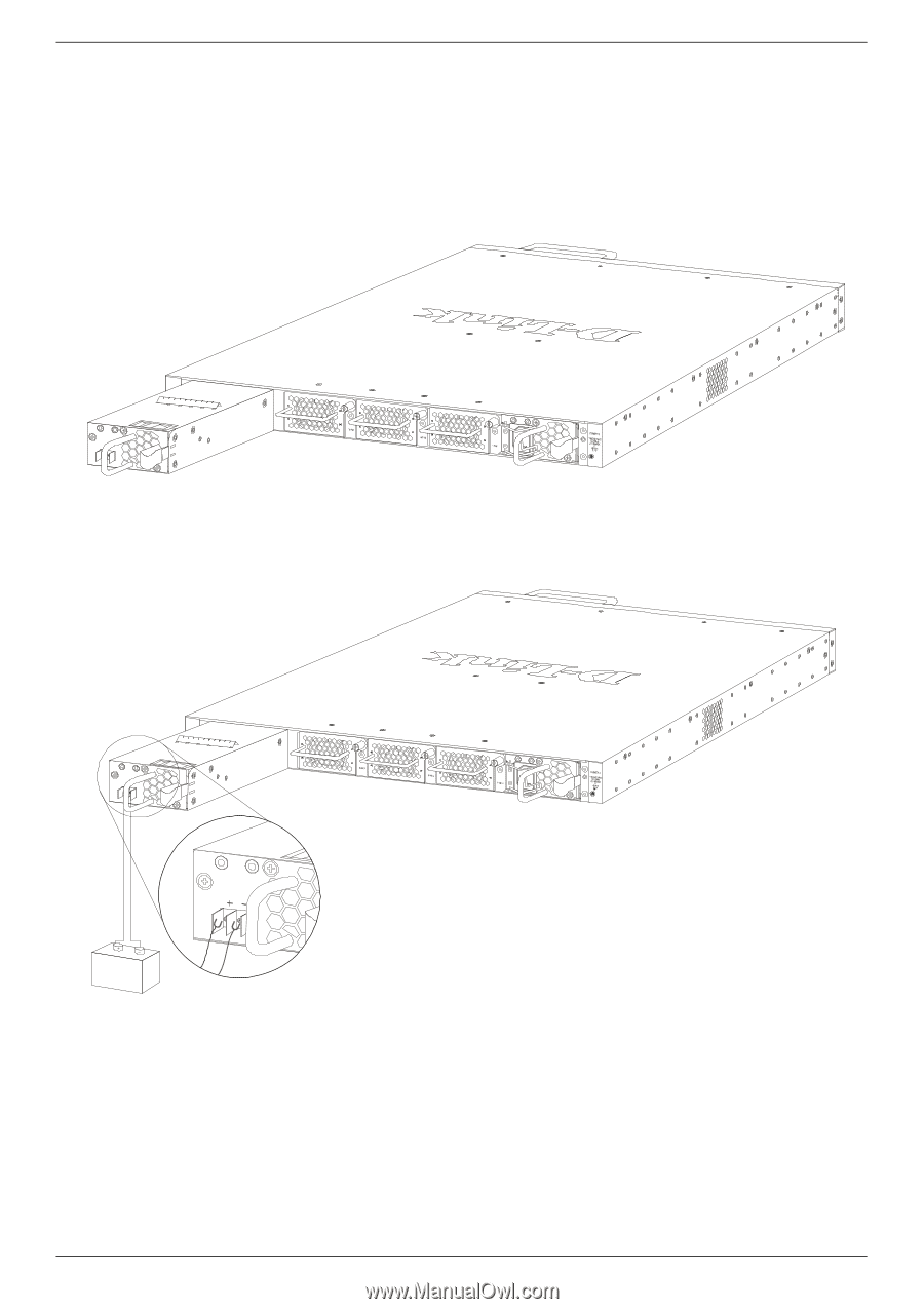
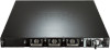
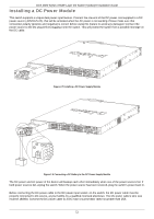
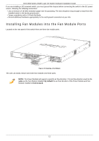
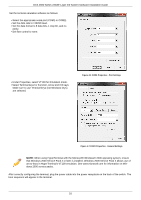
DXS-3600 Series 10GbE Layer 2/3 Switch Hardware Installation Guide Installing a DC Power Module This switch supports a unique dual power input feature. Connect the one end of the DC power cord supplied to a DC power source (-48VDC/5.2A), that will be activated when the AC power is not working. Please make sure that connection polarity (positive and negative) is correct before using this feature to avoid any damaged. Connect the power source to the DC plug before plugging it into the switch. This will protect the switch from a possible shortage on the DC cable. Figure 2-7 Installing a DC Power Supply Module Figure 2-8 Connecting a DC Battery to the DC Power Supply Module The DC power and AC power of the device will backup each other immediately when one of the power sources fail. If both power sources fail, unplug the switch. When the power source has been restored, plug the switch's power back in. Before connecting the DC power cable to the DC power input socket, on the switch, the DC power cable must be properly connected to DC source, at your facility, by a qualified, licensed electrician. The DC power cable's wire size must be 18AWG. Connect the DC power cable to a DC main circuit breaker rated no greater than 15A. 11
-
 1
1 -
2
-
3
-
4
-
5
-
6
-
7
-
8
-
9
-
10
-
11
-
 12
12 -
 13
13 -
 14
14 -
 15
15 -
 16
16 -
 17
17 -
 18
18 -
 19
19 -
 20
20 -
 21
21 -
 22
22 -
23
-
24
-
25
-
26
-
27
-
28
-
29
-
30
-
31
-
32
-
33
-
34
-
35
-
36
 |
 |