D-Link DXS-3600-EM-STACK Hardware Installation Guide - Page 27
Management Information Base (MIB), Connecting using the Web User Interface
 |
View all D-Link DXS-3600-EM-STACK manuals
Add to My Manuals
Save this manual to your list of manuals |
Page 27 highlights
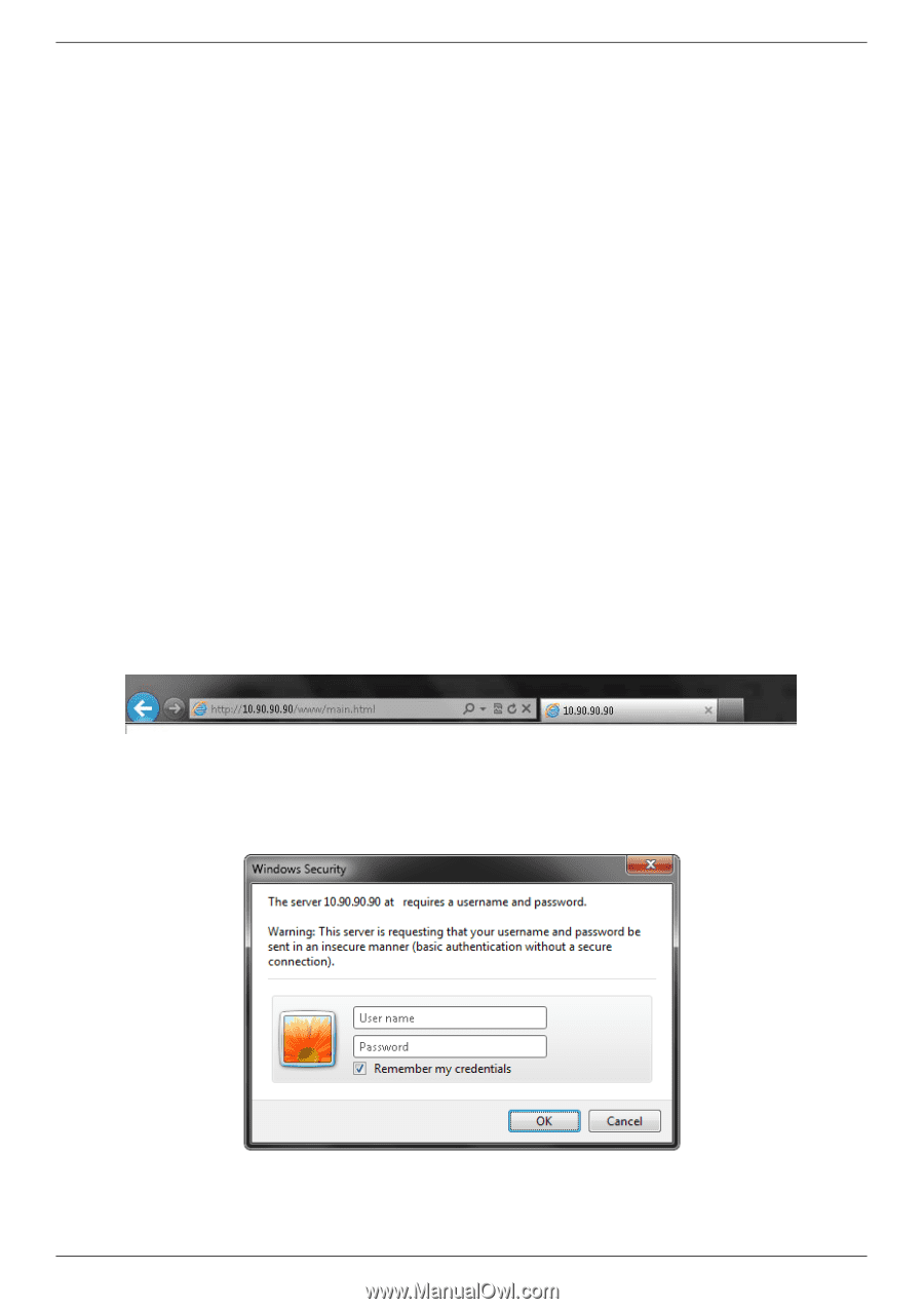
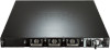
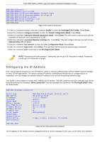
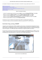
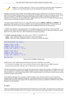
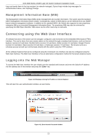
DXS-3600 Series 10GbE Layer 2/3 Switch Hardware Installation Guide traps and sends them to the trap recipient (or network manager). Typical traps include trap messages for Authentication Failure, and Topology Change. Management Information Base (MIB) The Management Information Base (MIB) stores management and counter information. The switch uses the standard MIB-II Management Information Base module. Consequently, values for MIB objects can be retrieved from any SNMPbased network management software. In addition to the standard MIB-II, the Switch also supports its own proprietary enterprise MIB as an extended Management Information Base. The proprietary MIB may also be retrieved by specifying the MIB Object Identifier. MIB values can be either read-only or read-write. Connecting using the Web User Interface All software functions of the switch can be managed, configured, and monitored via the embedded Web-based (HTML) interface. This can be done from any remote station on the network through a standard web browser, such as Internet Explorer (version 6.0 and later), Mozilla Firefox (version 3.0 and later), Safari (version 4.0 and later), Google Chrome (version 5.0 and later), Opera (version 9.0 and later), or Netscape (version 7.0 and later). The browser acts as a universal access tool and can communicate directly with the switch using the HTTP protocol. All the software features that can be configured using the Command Line Interface can also be configured using the Web User Interface. The Web User Interface is thus an alternative configuration method for the lesser analytical users. Logging onto the Web Manager To access the Web User Interface the user simply runs the standard web browser and enter the Switch's IP address into the address bar of the browser and press the 'Enter' key. Figure 4-10 Displays entering the IP address in Internet Explorer This will open the user authentication window, as seen below. Figure 4-11 Enter Network Password window 21
-
 1
1 -
2
-
3
-
4
-
5
-
6
-
7
-
8
-
9
-
10
-
11
-
12
-
13
-
14
-
15
-
16
-
17
-
18
-
19
-
20
-
21
-
 22
22 -
 23
23 -
 24
24 -
 25
25 -
 26
26 -
 27
27 -
 28
28 -
 29
29 -
 30
30 -
 31
31 -
 32
32 -
33
-
34
-
35
-
36
 |
 |