Dell Alienware M15x Service Manual - Page 102
Removing the System Board
 |
UPC - 074450000064
View all Dell Alienware M15x manuals
Add to My Manuals
Save this manual to your list of manuals |
Page 102 highlights
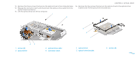
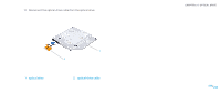
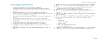
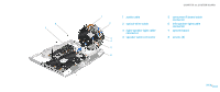
Removing the System Board 1. Follow the instructions in "Before You Begin" on page 6. 2. Remove the battery pack (see "Removing the Battery Pack" on page 11). 3. Remove the compartment door (see "Removing the Compartment Door" on page 14). 4. Remove the hard drive (see "Removing the Hard Drive" on page 17). 5. Disconnect the coin-cell battery cable from the system board connector (see "Removing the Coin-Cell Battery on page 27). 6. Remove the memory module(s) (see "Removing the Memory Module(s)" on page 21). 7. Remove the palm rest (see "Removing the Palm Rest" on page 38). 8. Remove the center control cover (see "Removing the Center Control Cover" on page 30). 9. Remove the keyboard (see "Removing the Keyboard" on page 34). 10. Remove the air vents (see "Removing the Air Vents" on page 42). 11. Remove the display assembly (see "Removing the Display Assembly" on page 73). 12. Remove the magnesium cover (see "Removing the Magnesium Cover" on page 21). CHAPTER 22: SYSTEM BOARD 13. Remove the half Mini-Card (see "Removing the Half Mini-Card" on page 46). 14. Remove the full Mini-Card (see "Removing the Full Mini-Card" on page 48). 15. Remove the processor fan and heat sink assembly (see "Removing the Processor Fan and Heat Sink Assembly" on page 52). 16. Remove the processor (see "Removing the Processor" on page 57). 17. Remove the graphics card fan (see "Removing the Graphics Card Fan" on page 61). 18. Remove the graphics card heat sink (see "Removing the Graphics Card Heat Sink" on page 65). 19. Remove the graphics card (see "Removing the Graphics Card" on page 69). 20. Disconnect the following cables from their respective system board connectors: • audio cable • optical-drive cable • speaker cable • left- and right-speaker light cable • consumer IR board cable 21. Remove the five screws that secure the system board to the computer base. 22. Lift the system board at an angle and remove it from the computer base. 0102 /0102
-
 1
1 -
2
-
3
-
4
-
5
-
6
-
7
-
8
-
9
-
10
-
11
-
12
-
13
-
14
-
15
-
16
-
17
-
18
-
19
-
20
-
21
-
22
-
23
-
24
-
25
-
26
-
27
-
28
-
29
-
30
-
31
-
32
-
33
-
34
-
35
-
36
-
37
-
38
-
39
-
40
-
41
-
42
-
43
-
44
-
45
-
46
-
47
-
48
-
49
-
50
-
51
-
52
-
53
-
54
-
55
-
56
-
57
-
58
-
59
-
60
-
61
-
62
-
63
-
64
-
65
-
66
-
67
-
68
-
69
-
70
-
71
-
72
-
73
-
74
-
75
-
76
-
77
-
78
-
79
-
80
-
81
-
82
-
83
-
84
-
85
-
86
-
87
-
88
-
89
-
90
-
91
-
92
-
93
-
94
-
95
-
96
-
 97
97 -
 98
98 -
 99
99 -
 100
100 -
 101
101 -
 102
102 -
 103
103 -
 104
104 -
 105
105 -
 106
106 -
 107
107 -
108
-
109
-
110
-
111
-
112
-
113
-
114
-
115
-
116
-
117
-
118
 |
 |