Dell Alienware M15x Service Manual - Page 53
processor fan and heat sink, assembly cable connector, assembly, captive screws 4
 |
UPC - 074450000064
View all Dell Alienware M15x manuals
Add to My Manuals
Save this manual to your list of manuals |
Page 53 highlights
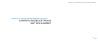
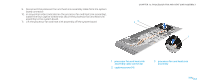
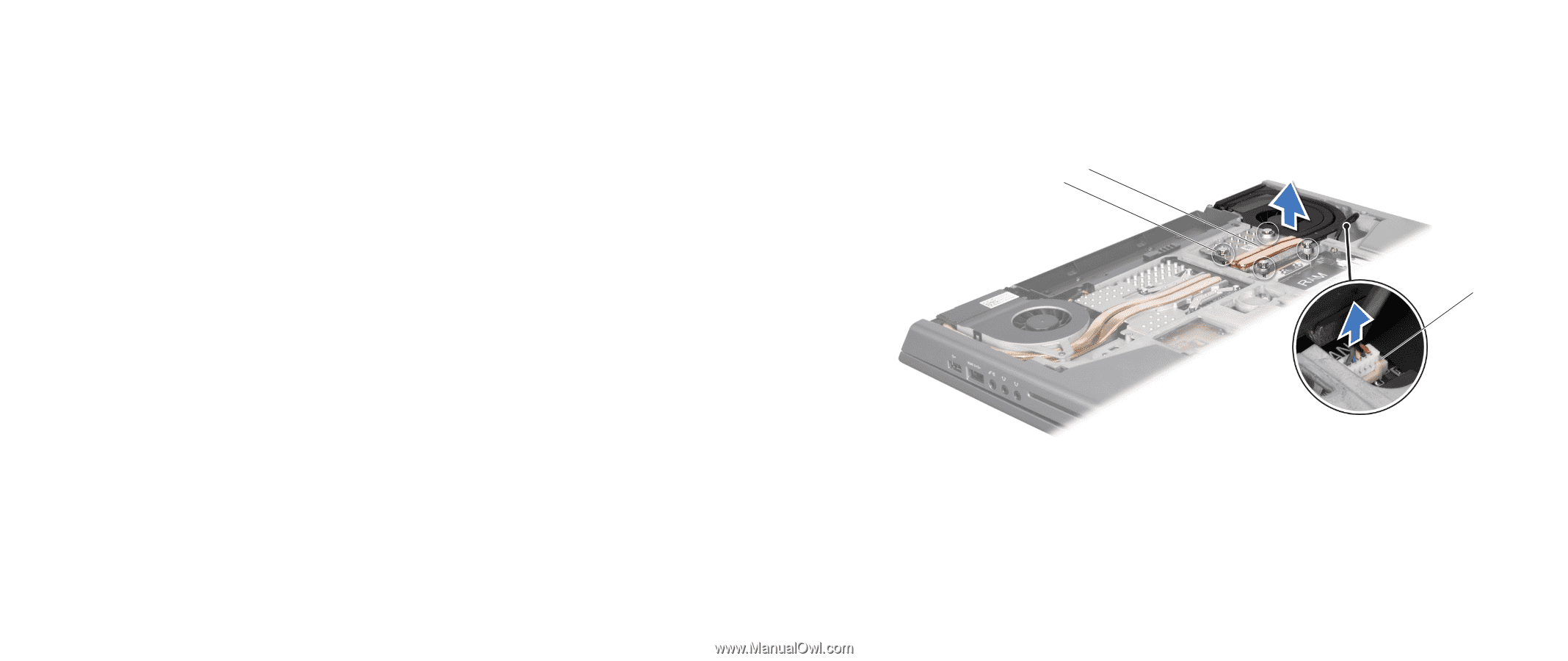
9. Disconnect the processor fan and heat sink assembly cable from the system board connector. 10. In sequential order (indicated on the processor fan and heat sink assembly), loosen the four captive screws that secure the processor fan and heat sink assembly to the system board. 11. Lift the processor fan and heat sink assembly off the system board. CHAPTER 12: PROCESSOR FAN AND HEAT SINK ASSEMBLY 23 1 1 processor fan and heat sink assembly cable connector 2 captive screws (4) 3 processor fan and heat sink assembly 053 /053
-
 1
1 -
2
-
3
-
4
-
5
-
6
-
7
-
8
-
9
-
10
-
11
-
12
-
13
-
14
-
15
-
16
-
17
-
18
-
19
-
20
-
21
-
22
-
23
-
24
-
25
-
26
-
27
-
28
-
29
-
30
-
31
-
32
-
33
-
34
-
35
-
36
-
37
-
38
-
39
-
40
-
41
-
42
-
43
-
44
-
45
-
46
-
47
-
 48
48 -
 49
49 -
 50
50 -
 51
51 -
 52
52 -
 53
53 -
 54
54 -
 55
55 -
 56
56 -
 57
57 -
 58
58 -
59
-
60
-
61
-
62
-
63
-
64
-
65
-
66
-
67
-
68
-
69
-
70
-
71
-
72
-
73
-
74
-
75
-
76
-
77
-
78
-
79
-
80
-
81
-
82
-
83
-
84
-
85
-
86
-
87
-
88
-
89
-
90
-
91
-
92
-
93
-
94
-
95
-
96
-
97
-
98
-
99
-
100
-
101
-
102
-
103
-
104
-
105
-
106
-
107
-
108
-
109
-
110
-
111
-
112
-
113
-
114
-
115
-
116
-
117
-
118
 |
 |
053
053
/
CHAPTER 12: PROCESSOR FAN AND HEAT SINK ASSEMBLY
3
2
1
1
processor fan and heat sink
assembly cable connector
3
processor fan and heat sink
assembly
2
captive screws (4)
Disconnect the processor fan and heat sink assembly cable from the system
9.
board connector.
In sequential order (indicated on the processor fan and heat sink assembly),
10.
loosen the four captive screws that secure the processor fan and heat sink
assembly to the system board.
Lift the processor fan and heat sink assembly off the system board.
11.