Dell Alienware M15x Service Manual - Page 47
Replacing the Half Mini-Card
 |
UPC - 074450000064
View all Dell Alienware M15x manuals
Add to My Manuals
Save this manual to your list of manuals |
Page 47 highlights
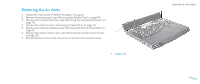
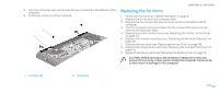
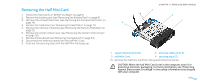
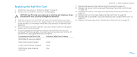
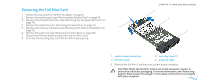
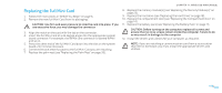
Replacing the Half Mini-Card 1. Follow the instructions in "Before You Begin" on page 6. 2. Remove the new half Mini-Card from its packaging. CAUTION: Use firm and even pressure to slide the card into place. If you use excessive force, you may damage the connector. 3. Align the notch on the card with the tab on the system board connector. 4. Insert the half Mini-Card at a 45-degree angle into the appropriate system board connector. For example, the WLAN card connector is labeled WLAN and so on. 5. Press the other end of the half Mini-Card down into the slot on the system board until it clicks into place. 6. Connect the appropriate antenna cables to the half Mini-Card you are installing. The following table provides the antenna cable color scheme for the half Mini-Card supported by your computer. Connectors on the Mini-Card Antenna Cable Color Scheme WLAN (2 or 3 antenna cables): Main WLAN (white triangle) white Auxiliary WLAN (black triangle) black MIMO WLAN (gray triangle) gray (optional) CHAPTER 11: WIRELESS MINI-CARD(S) 7. Replace the keyboard (see "Replacing the Keyboard" on page 35). 8. Replace the center control cover (see "Replacing the Center Control Cover" on page 31). 9. Replace the memory module(s) (see "Replacing the Memory Module(s)" on page 21). 10. Replace the hard drive (see "Replacing the Hard Drive" on page 18). 11. Replace the compartment door (see "Replacing the Compartment Door" on page 14). 12. Replace the battery pack (see "Replacing the Battery Pack" on page 11). 047 /047
-
 1
1 -
2
-
3
-
4
-
5
-
6
-
7
-
8
-
9
-
10
-
11
-
12
-
13
-
14
-
15
-
16
-
17
-
18
-
19
-
20
-
21
-
22
-
23
-
24
-
25
-
26
-
27
-
28
-
29
-
30
-
31
-
32
-
33
-
34
-
35
-
36
-
37
-
38
-
39
-
40
-
41
-
 42
42 -
 43
43 -
 44
44 -
 45
45 -
 46
46 -
 47
47 -
 48
48 -
 49
49 -
 50
50 -
 51
51 -
 52
52 -
53
-
54
-
55
-
56
-
57
-
58
-
59
-
60
-
61
-
62
-
63
-
64
-
65
-
66
-
67
-
68
-
69
-
70
-
71
-
72
-
73
-
74
-
75
-
76
-
77
-
78
-
79
-
80
-
81
-
82
-
83
-
84
-
85
-
86
-
87
-
88
-
89
-
90
-
91
-
92
-
93
-
94
-
95
-
96
-
97
-
98
-
99
-
100
-
101
-
102
-
103
-
104
-
105
-
106
-
107
-
108
-
109
-
110
-
111
-
112
-
113
-
114
-
115
-
116
-
117
-
118
 |
 |