Dell Alienware M15x Service Manual - Page 34
Removing the Keyboard
 |
UPC - 074450000064
View all Dell Alienware M15x manuals
Add to My Manuals
Save this manual to your list of manuals |
Page 34 highlights
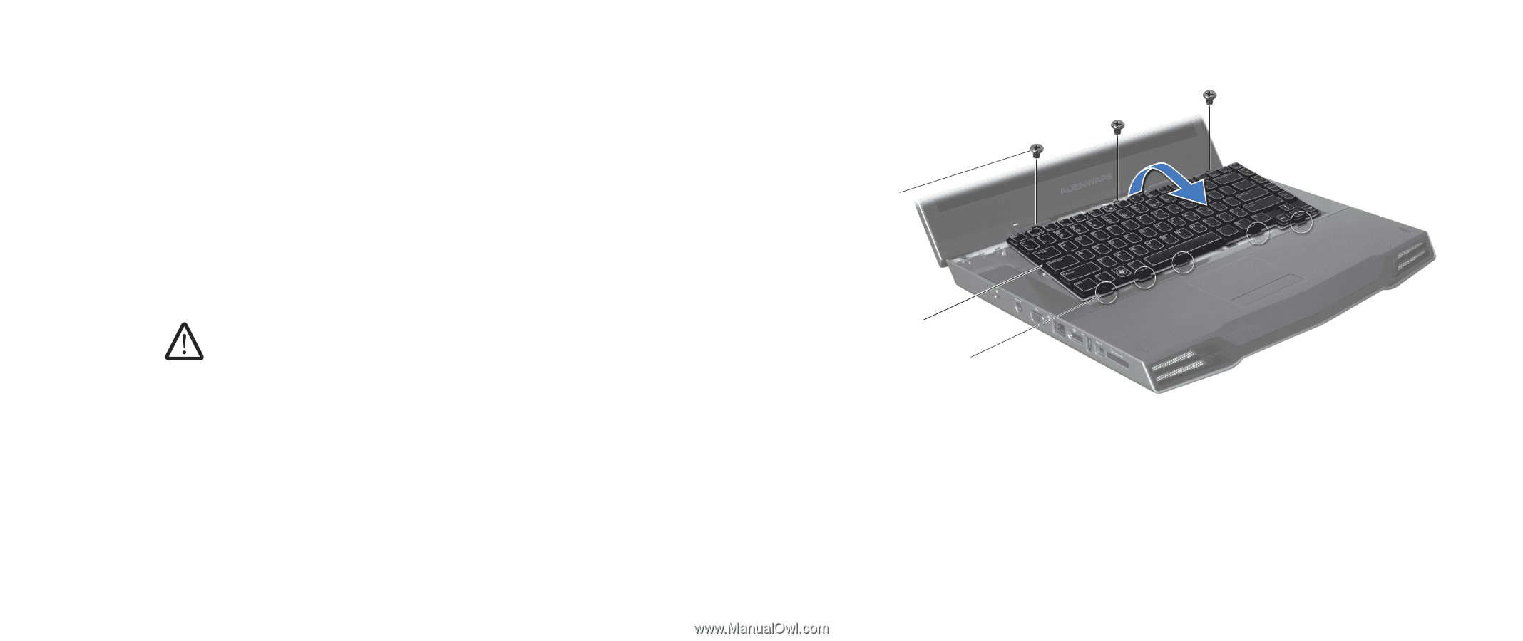
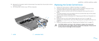
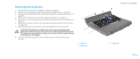
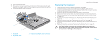
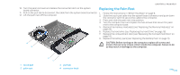
Removing the Keyboard 1. Follow the instructions in "Before You Begin" on page 6. 2. Remove the battery pack (see "Removing the Battery Pack" on page 11). 3. Remove the compartment door (see "Removing the Compartment Door" on page 14). 4. Remove the hard drive (see "Removing the Hard Drive" on page 17). 5. Remove the memory module(s) (see "Removing the Memory Module(s)" on page 21). 6. Remove the center control cover (see "Removing the Center Control Cover" on page 30). 7. Remove the three screws that secure the keyboard to the computer. CAUTION: Be extremely careful when removing and handling the keyboard. Failure to do so could result in scratching the display panel. The keyboard along with the cables that attach it to the system board connector are very fragile. 8. Lift and slide the keyboard until the tabs come out of the slots on the chassis. 3 2 1 1 tabs (5) 2 keyboard CHAPTER 8: KEYBOARD 3 screws (3) 034 /034
-
 1
1 -
2
-
3
-
4
-
5
-
6
-
7
-
8
-
9
-
10
-
11
-
12
-
13
-
14
-
15
-
16
-
17
-
18
-
19
-
20
-
21
-
22
-
23
-
24
-
25
-
26
-
27
-
28
-
 29
29 -
 30
30 -
 31
31 -
 32
32 -
 33
33 -
 34
34 -
 35
35 -
 36
36 -
 37
37 -
 38
38 -
 39
39 -
40
-
41
-
42
-
43
-
44
-
45
-
46
-
47
-
48
-
49
-
50
-
51
-
52
-
53
-
54
-
55
-
56
-
57
-
58
-
59
-
60
-
61
-
62
-
63
-
64
-
65
-
66
-
67
-
68
-
69
-
70
-
71
-
72
-
73
-
74
-
75
-
76
-
77
-
78
-
79
-
80
-
81
-
82
-
83
-
84
-
85
-
86
-
87
-
88
-
89
-
90
-
91
-
92
-
93
-
94
-
95
-
96
-
97
-
98
-
99
-
100
-
101
-
102
-
103
-
104
-
105
-
106
-
107
-
108
-
109
-
110
-
111
-
112
-
113
-
114
-
115
-
116
-
117
-
118
 |
 |