Dell Alienware M15x Service Manual - Page 75
Replacing the Display Assembly - hinge
 |
UPC - 074450000064
View all Dell Alienware M15x manuals
Add to My Manuals
Save this manual to your list of manuals |
Page 75 highlights
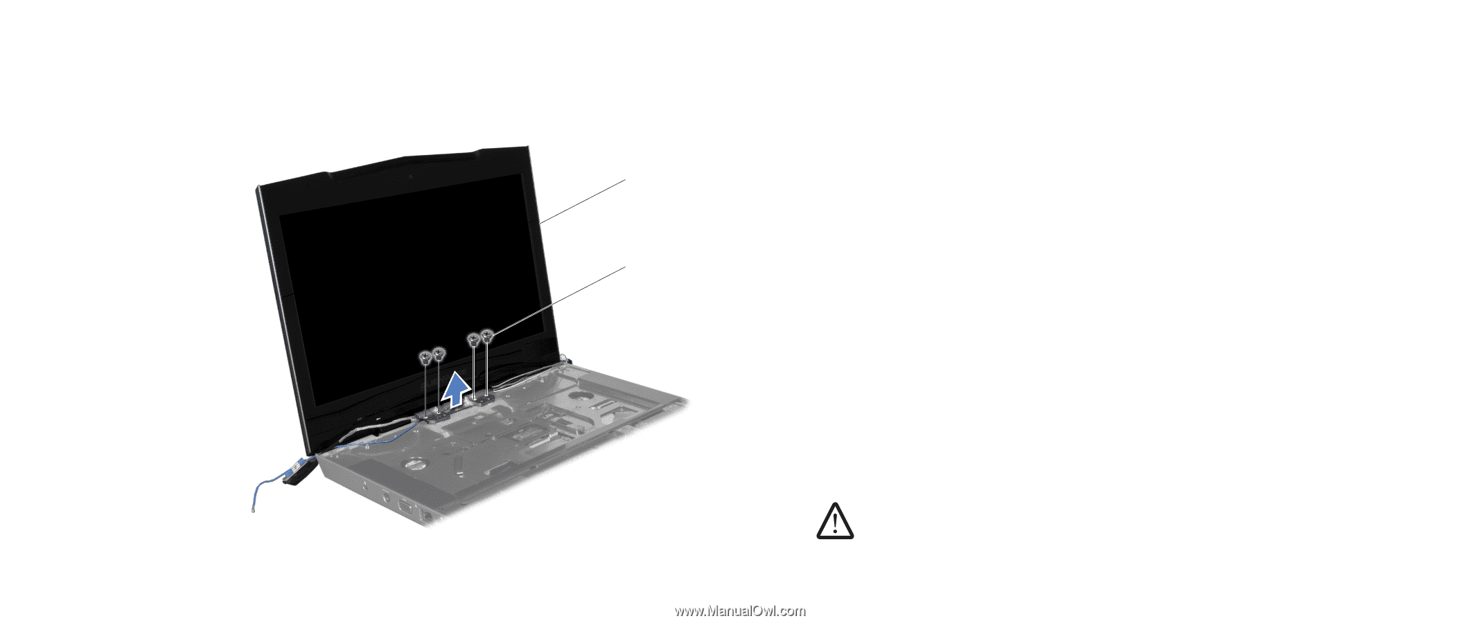
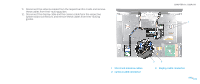
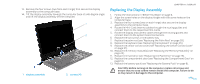
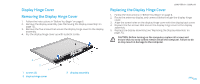
13. Remove the four screws (two from each hinge) that secure the display assembly to the computer base. 14. Tilt the display assembly towards the computer base at a 45-degree angle and lift the display assembly off the computer. 1 2 1 display assembly 2 screws (4) CHAPTER 17: DISPLAY Replacing the Display Assembly 1. Follow the instructions in "Before You Begin" on page 6. 2. Align the screw holes on the display hinges with the screw holes on the computer base. 3. Replace the four screws (two on each hinge) that secure the display assembly to the computer base. 4. Route the Mini-Card antenna cables through the routing guides and connect them to the respective Mini-Cards. 5. Route the display and camera cables through the routing guides and connect them to the system board connectors. 6. Replace the two screws in the battery bay. 7. Replace the palm rest (see "Replacing the Palm Rest" on page 39). 8. Replace the keyboard (see "Replacing the Keyboard" on page 35). 9. Replace the center control cover (see "Replacing the Center Control Cover" on page 31). 10. Replace the memory module(s) (see "Replacing the Memory Module(s)" on page 23). 11. Replace the hard drive (see "Replacing the Hard Drive" on page 18). 12. Replace the compartment door (see "Replacing the Compartment Door" on page 14). 13. Replace the battery pack (see "Replacing the Battery Pack" on page 8). CAUTION: Before turning on the computer, replace all screws and ensure that no stray screws remain inside the computer. Failure to do so may result in damage to the computer. 075 /075
-
 1
1 -
2
-
3
-
4
-
5
-
6
-
7
-
8
-
9
-
10
-
11
-
12
-
13
-
14
-
15
-
16
-
17
-
18
-
19
-
20
-
21
-
22
-
23
-
24
-
25
-
26
-
27
-
28
-
29
-
30
-
31
-
32
-
33
-
34
-
35
-
36
-
37
-
38
-
39
-
40
-
41
-
42
-
43
-
44
-
45
-
46
-
47
-
48
-
49
-
50
-
51
-
52
-
53
-
54
-
55
-
56
-
57
-
58
-
59
-
60
-
61
-
62
-
63
-
64
-
65
-
66
-
67
-
68
-
69
-
 70
70 -
 71
71 -
 72
72 -
 73
73 -
 74
74 -
 75
75 -
 76
76 -
 77
77 -
 78
78 -
 79
79 -
 80
80 -
81
-
82
-
83
-
84
-
85
-
86
-
87
-
88
-
89
-
90
-
91
-
92
-
93
-
94
-
95
-
96
-
97
-
98
-
99
-
100
-
101
-
102
-
103
-
104
-
105
-
106
-
107
-
108
-
109
-
110
-
111
-
112
-
113
-
114
-
115
-
116
-
117
-
118
 |
 |