Dell Alienware M15x Service Manual - Page 88
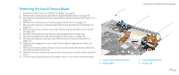
Removing the Input/Output Board
 |
UPC - 074450000064
View all Dell Alienware M15x manuals
Add to My Manuals
Save this manual to your list of manuals |
Page 88 highlights
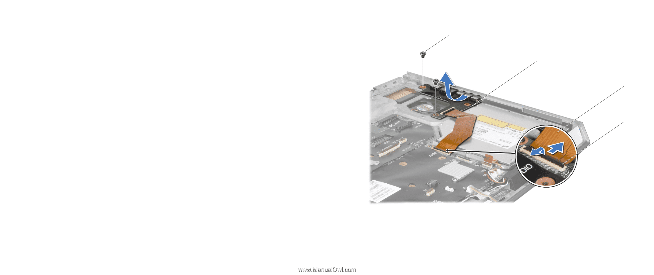
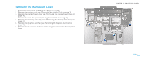
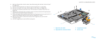
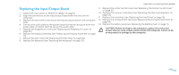
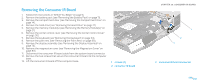
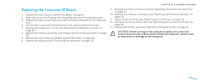
Removing the Input/Output Board 1. Follow the instructions in "Before You Begin" on page 6. 2. Remove the battery pack (see "Removing the Battery Pack" on page 11). 3. Remove the compartment door (see "Removing the Compartment Door" on page 14). 4. Remove the hard drive (see "Removing the Hard Drive" on page 17). 5. Remove the memory module(s) (see "Removing the Memory Module(s)" on page 21). 6. Remove the center control cover (see "Removing the Center Control Cover" on page 30). 7. Remove the keyboard (see "Removing the Keyboard" on page 34). 8. Remove the palm rest (see "Removing the Palm Rest" on page 38). 9. Remove the display assembly (see "Removing the Display Assembly" on page 73). 10. Remove the magnesium cover (see "Removing the Magnesium Cover" on page 83). 11. Release the audio cable connector latch to disconnect the audio cable from the system board connector. 12. Remove the two screws that secure the input/output board to the computer base. 13. Tilt the input/output board at an angle and lift it out of the computer base. 4 1 audio cable connector latch 2 audio cable CHAPTER 19: INPUT/OUTPUT BOARD 3 2 1 3 input/output board 4 screws (2) 088 /088
-
 1
1 -
2
-
3
-
4
-
5
-
6
-
7
-
8
-
9
-
10
-
11
-
12
-
13
-
14
-
15
-
16
-
17
-
18
-
19
-
20
-
21
-
22
-
23
-
24
-
25
-
26
-
27
-
28
-
29
-
30
-
31
-
32
-
33
-
34
-
35
-
36
-
37
-
38
-
39
-
40
-
41
-
42
-
43
-
44
-
45
-
46
-
47
-
48
-
49
-
50
-
51
-
52
-
53
-
54
-
55
-
56
-
57
-
58
-
59
-
60
-
61
-
62
-
63
-
64
-
65
-
66
-
67
-
68
-
69
-
70
-
71
-
72
-
73
-
74
-
75
-
76
-
77
-
78
-
79
-
80
-
81
-
82
-
 83
83 -
 84
84 -
 85
85 -
 86
86 -
 87
87 -
 88
88 -
 89
89 -
 90
90 -
 91
91 -
 92
92 -
 93
93 -
94
-
95
-
96
-
97
-
98
-
99
-
100
-
101
-
102
-
103
-
104
-
105
-
106
-
107
-
108
-
109
-
110
-
111
-
112
-
113
-
114
-
115
-
116
-
117
-
118
 |
 |