Dell Alienware M15x Service Manual - Page 89
Replacing the Input/Output Board
 |
UPC - 074450000064
View all Dell Alienware M15x manuals
Add to My Manuals
Save this manual to your list of manuals |
Page 89 highlights
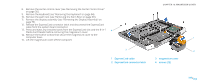
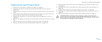
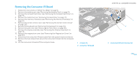
Replacing the Input/Output Board 1. Follow the instructions in "Before You Begin" on page 6. 2. Align the connectors on the input/output board with the slots on the computer. 3. Replace the two screws that secure the input/output board to the computer base. 4. Connect the audio cable to the system board connector and push down the audio cable connector latch to secure the audio cable. 5. Replace the magnesium cover (see "Replacing the Magnesium Cover" on page 85). 6. Replace the display assembly (see "Replacing the Display Assembly" on page 75). 7. Replace the palm rest (see "Replacing the Palm Rest" on page 39). 8. Replace the keyboard (see "Replacing the Keyboard" on page 35). CHAPTER 19: INPUT/OUTPUT BOARD 9. Replace the center control cover (see "Replacing the Center Control Cover" on page 31). 10. Replace the memory module(s) (see "Replacing the Memory Module(s)" on page 23). 11. Replace the hard drive (see "Replacing the Hard Drive" on page 18). 12. Replace the compartment door (see "Replacing the Compartment Door" on page 14). 13. Replace the battery pack (see "Replacing the Battery Pack" on page 11). CAUTION: Before turning on the computer, replace all screws and ensure that no stray screws remain inside the computer. Failure to do so may result in damage to the computer. 089 /089
-
 1
1 -
2
-
3
-
4
-
5
-
6
-
7
-
8
-
9
-
10
-
11
-
12
-
13
-
14
-
15
-
16
-
17
-
18
-
19
-
20
-
21
-
22
-
23
-
24
-
25
-
26
-
27
-
28
-
29
-
30
-
31
-
32
-
33
-
34
-
35
-
36
-
37
-
38
-
39
-
40
-
41
-
42
-
43
-
44
-
45
-
46
-
47
-
48
-
49
-
50
-
51
-
52
-
53
-
54
-
55
-
56
-
57
-
58
-
59
-
60
-
61
-
62
-
63
-
64
-
65
-
66
-
67
-
68
-
69
-
70
-
71
-
72
-
73
-
74
-
75
-
76
-
77
-
78
-
79
-
80
-
81
-
82
-
83
-
 84
84 -
 85
85 -
 86
86 -
 87
87 -
 88
88 -
 89
89 -
 90
90 -
 91
91 -
 92
92 -
 93
93 -
 94
94 -
95
-
96
-
97
-
98
-
99
-
100
-
101
-
102
-
103
-
104
-
105
-
106
-
107
-
108
-
109
-
110
-
111
-
112
-
113
-
114
-
115
-
116
-
117
-
118
 |
 |