Dell Alienware M15x Service Manual - Page 57
Removing the Processor
 |
UPC - 074450000064
View all Dell Alienware M15x manuals
Add to My Manuals
Save this manual to your list of manuals |
Page 57 highlights
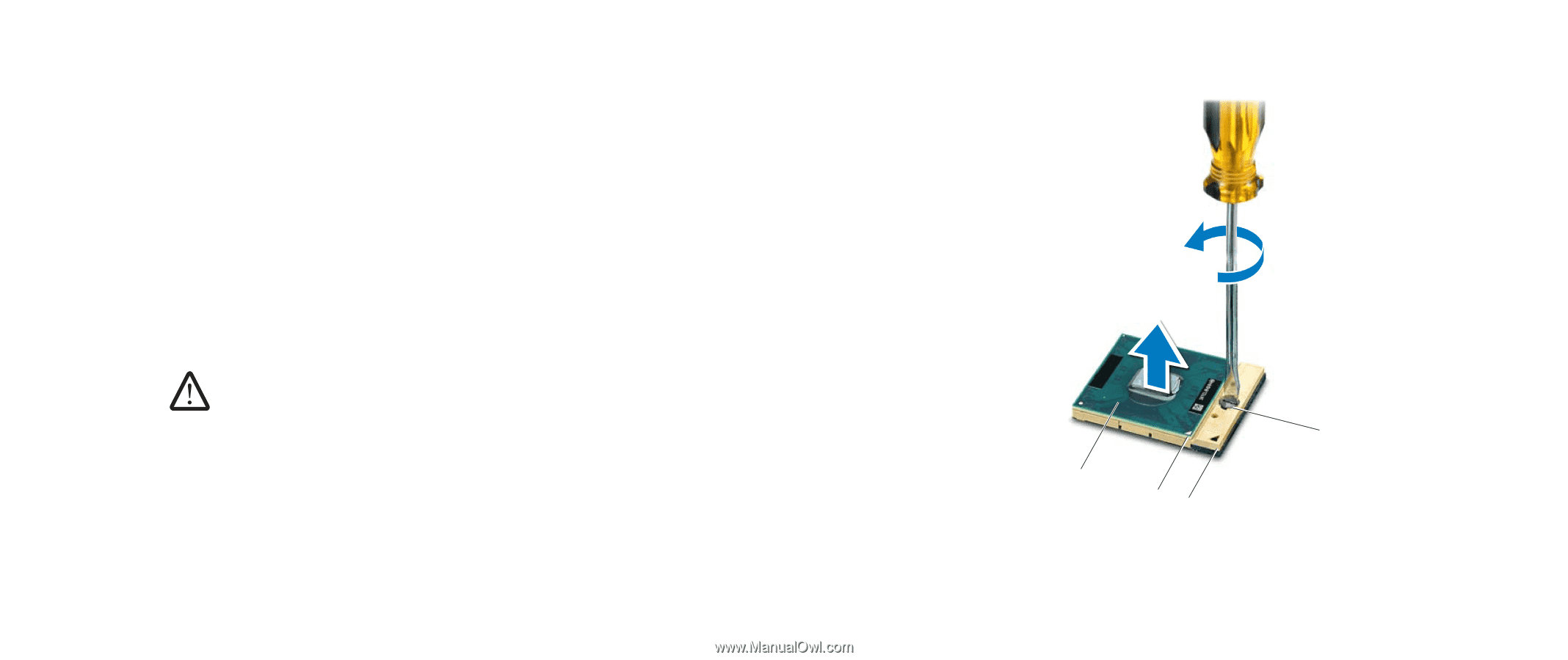
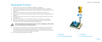
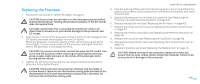
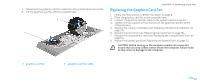
Removing the Processor 1. Follow the instructions in "Before You Begin" on page 6. 2. Remove the battery pack (see "Removing the Battery Pack" on page 11). 3. Remove the compartment door (see "Removing the Compartment Door" on page 14). 4. Remove the hard drive (see "Removing the Hard Drive" on page 17). 5. Remove the memory module(s) (see "Removing the Memory Module(s)" on page 21). 6. Remove the center control cover (see "Removing the Center Control Cover" on page 30). 7. Remove the right air-vent (see "Removing the Air Vents" on page 42). 8. Remove the processor fan and heat sink assembly (see "Removing the Processor Fan and Heat Sink Assembly" on page 52). CAUTION: When removing the processor, pull it straight up. Be careful not to bend the pins on the processor. 9. To loosen the ZIF socket, use a small flat-blade screwdriver and rotate the ZIF-socket cam screw counterclockwise until it comes to the cam stop. The ZIF-socket cam screw secures the processor to the system board. Take note of the arrow on the ZIF-socket cam screw. 10. Lift the processor off the ZIF socket. CHAPTER 13: PROCESSOR 1 1 processor 2 pin-1 corner of processor 4 23 3 ZIF socket 4 ZIF-socket cam screw 057 /057
-
 1
1 -
2
-
3
-
4
-
5
-
6
-
7
-
8
-
9
-
10
-
11
-
12
-
13
-
14
-
15
-
16
-
17
-
18
-
19
-
20
-
21
-
22
-
23
-
24
-
25
-
26
-
27
-
28
-
29
-
30
-
31
-
32
-
33
-
34
-
35
-
36
-
37
-
38
-
39
-
40
-
41
-
42
-
43
-
44
-
45
-
46
-
47
-
48
-
49
-
50
-
51
-
 52
52 -
 53
53 -
 54
54 -
 55
55 -
 56
56 -
 57
57 -
 58
58 -
 59
59 -
 60
60 -
 61
61 -
 62
62 -
63
-
64
-
65
-
66
-
67
-
68
-
69
-
70
-
71
-
72
-
73
-
74
-
75
-
76
-
77
-
78
-
79
-
80
-
81
-
82
-
83
-
84
-
85
-
86
-
87
-
88
-
89
-
90
-
91
-
92
-
93
-
94
-
95
-
96
-
97
-
98
-
99
-
100
-
101
-
102
-
103
-
104
-
105
-
106
-
107
-
108
-
109
-
110
-
111
-
112
-
113
-
114
-
115
-
116
-
117
-
118
 |
 |