Dell Alienware m17 R2 Service Manual
Dell Alienware m17 R2 Manual
 |
View all Dell Alienware m17 R2 manuals
Add to My Manuals
Save this manual to your list of manuals |
Dell Alienware m17 R2 manual content summary:
- Dell Alienware m17 R2 | Service Manual - Page 1
Alienware m17 R2 Service Manual Regulatory Model: P41E Regulatory Type: P41E001 June 2020 Rev. A01 - Dell Alienware m17 R2 | Service Manual - Page 2
data and tells you how to avoid the problem. WARNING: A WARNING indicates a potential for property damage, personal injury, or death. © 2019-2020 Dell Inc. or its subsidiaries. All rights reserved. Dell, EMC, and other trademarks are trademarks of Dell Inc. or its subsidiaries. Other trademarks may - Dell Alienware m17 R2 | Service Manual - Page 3
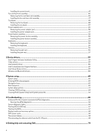
instructions...5 Before working inside your computer...5 Before you begin ...5 Electrostatic discharge-ESD protection...5 ESD field service solid-state drive...17 Coin-cell battery...18 Removing the coin-cell battery...18 Installing the coin-cell battery...19 Speakers...20 Removing the speakers... - Dell Alienware m17 R2 | Service Manual - Page 4
drivers...59 4 System setup...60 System setup...60 Entering BIOS setup program...60 Navigation keys...60 Boot Sequence...60 System setup options...61 Clearing CMOS settings...64 Clearing BIOS (System Setup) and System passwords...64 5 Troubleshooting port 68 6 Getting help and contacting Dell...70 4 - Dell Alienware m17 R2 | Service Manual - Page 5
troubleshooting and repairs as authorized or directed by the Dell technical assistance team. Damage due to servicing that is not authorized by Dell is not covered by your warranty. See the safety instructions obvious, such as intermittent problems or a shortened product life span. As the industry - Dell Alienware m17 R2 | Service Manual - Page 6
higher than in previous Dell products. For this The more difficult type of damage to recognize and troubleshoot is the intermittent (also called latent or "walking and bonding wire between your skin, the ESD mat, and the hardware is known as bonding. Use only Field Service kits with a wrist strap - Dell Alienware m17 R2 | Service Manual - Page 7
service technicians use the traditional wired ESD grounding wrist strap and protective anti-static mat at all times when servicing Dell stable base, and point your toes out. 2. Tighten stomach muscles. Abdominal muscles support your spine when you lift, offsetting the force of the load. 3. Lift with - Dell Alienware m17 R2 | Service Manual - Page 8
drive 1 per M.2 2280 solidstate drive 2 Wireless-card bracket Left I/O-board M2x3 1 Display assembly Palm-rest assembly M2.5x5 6 Battery • Palm-rest assembly M2x4.5 8 • System board • Left I/O-board • Right I/O-board Keyboard-backlight Keyboard-controller M2x1.9 2 cable board - Dell Alienware m17 R2 | Service Manual - Page 9
2 2 2 4 Screw image System board Palm-rest assembly M2x3 5 Fan and heat-sink assembly System board M2x3 6 Solid-state drive support Palm-rest assembly M2x1.9 2 bracket Touchpad Palm-rest assembly M2x1.9 4 Power-adapter port Palm-rest assembly M2x3 2 bracket Power-button - Dell Alienware m17 R2 | Service Manual - Page 10
10 - Dell Alienware m17 R2 | Service Manual - Page 11
Steps 1. Remove the two screws (M2.5x5) that secure the base cover to the palm-rest assembly. 2. Loosen the six captive screws. 3. Using a plastic scribe, pry the base cover from the bottom-left corner and continue to work on the sides to open the base cover. 4. Lift the base cover off the palm-rest - Dell Alienware m17 R2 | Service Manual - Page 12
5. Disconnect the battery from the system board. 6. Press and hold the power button for 5 seconds to ground the computer and drain the flea power. Installing the base cover - Dell Alienware m17 R2 | Service Manual - Page 13
Steps 1. Connect the battery cable to the system board. 2. Slide the notches on the top of the base cover under the rear I/O-cover and snap the base cover into - Dell Alienware m17 R2 | Service Manual - Page 14
a M.2 2230 solid-state drive installed. NOTE: Depending on the configuration ordered your computer may have up to two M.2 cards installed. Supported card configurations per M.2 card slot: • M.2 2230 solid-state drive + 2230 mounting bracket • M.2 2280 solid-state drive The following image indicates - Dell Alienware m17 R2 | Service Manual - Page 15
these configurations are ordered. If these configurations are installed After Point-of-Sale (APOS), that is, after you purchase the computer; contact Dell support to purchase a thermal shield. NOTE: Before replacing the M.2 card take note that there are two M.2 card slots present on your computer - Dell Alienware m17 R2 | Service Manual - Page 16
Steps 1. Place and align the M.2 2230 mounting bracket on the palm-rest assembly. 2. Replace the screw (M2x3) that secures the M.2 2230 mounting bracket to the palm-rest assembly. 3. Align the notch on the M.2 2230 solid-state drive with the tab on the M.2 card slot on the system board. 4. Slide the - Dell Alienware m17 R2 | Service Manual - Page 17
a M.2 2280 solid-state drive installed. NOTE: Depending on the configuration ordered your computer may have up to two M.2 cards installed. Supported card configurations per M.2 card slot: • M.2 2230 solid-state drive + 2230 mounting bracket • M.2 2280 solid-state drive The following image indicates - Dell Alienware m17 R2 | Service Manual - Page 18
Sale (APOS), that is, after you purchase the computer; contact Dell support to purchase a thermal shield. NOTE: Before replacing the M.2 card inside your computer. Coin-cell battery Removing the coin-cell battery Prerequisites CAUTION: Removing the coin-cell battery resets the BIOS setup program's - Dell Alienware m17 R2 | Service Manual - Page 19
on the system board. 2. Peel and lift the coin-cell battery off the right I/O-board along with its cable. 3. Disconnect the coin-cell battery from the coin-cell battery cable. Installing the coin-cell battery Prerequisites If you are replacing a component, remove the existing component before - Dell Alienware m17 R2 | Service Manual - Page 20
onto the RTC marking on the right I/O-board. 3. Connect the coin-cell battery cable to the connector on the system board. Next steps 1. Install the base cover. 2. Follow the procedure in After working inside your computer. Speakers Removing - Dell Alienware m17 R2 | Service Manual - Page 21
speaker cable from the right I/O-board. 2. Lift the right speaker off the palm-rest assembly. 3. Remove the speaker cables from the routing guides on the palm-rest assembly. 4. Lift the left speaker off the palm-rest assembly. Installing the speakers Prerequisites If you are replacing a component - Dell Alienware m17 R2 | Service Manual - Page 22
assembly. NOTE: Ensure that the alignment posts are threaded through the rubber grommets on the speaker. 2. Route the speaker cable through the routing guides on the palm-rest assembly. 3. Using the alignment posts, place the right speaker on the palm-rest assembly. NOTE: Ensure that the alignment - Dell Alienware m17 R2 | Service Manual - Page 23
23 - Dell Alienware m17 R2 | Service Manual - Page 24
Steps 1. Peel and lift the Mylar covering the system board. 2. Disconnect and peel the Tron light cable from the system board and route the cable through the slot on the Mylar. NOTE: To prevent damaging your computer ensure the Tron light cable has been disconnected from the system board before - Dell Alienware m17 R2 | Service Manual - Page 25
Steps 1. Push the rear I/O-cover into the palm-rest assembly snapping it into place. NOTE: To avoiding damaging your computer, ensure the Tron light cable is not pinched and that the Mylar is pasted on the system board before snapping the rear I/O-cover into place. 2. Replace the two screws (M2.5x5) - Dell Alienware m17 R2 | Service Manual - Page 26
the base cover. 3. Remove the rear I/O-cover. About this task NOTE: The display assembly is a Hinge-up Display (HUD) and cannot be further disassembled. If components within the display assembly need to be replaced, the entire display assembly is to be replaced. The following image indicates the - Dell Alienware m17 R2 | Service Manual - Page 27
from the wireless card. 5. Peel the tapes securing the antenna cables to system board and left fan. 6. Remove the antenna cables from the routing guides on the left fan and system board. 7. Lift the latch and disconnect the display cable from the connector on the system board. 8. Disconnect the - Dell Alienware m17 R2 | Service Manual - Page 28
before performing the installation procedure. About this task NOTE: The display assembly is a Hinge-up Display (HUD) and cannot be further disassembled. If components within the display assembly need to be replaced, the entire display assembly is to be replaced. The following image indicates the - Dell Alienware m17 R2 | Service Manual - Page 29
Replace the six screws (M2.5x5) that secure the display assembly to the palm-rest assembly. 4. Route the following cables to the routing guides on the palm-rest assembly. • Display cable • G-sensor cable • Tobii eye tracker cable • Antenna cables 5. Place the computer face down. 6. Connect the Tobii - Dell Alienware m17 R2 | Service Manual - Page 30
provides the antenna-cable color scheme for the wireless card supported by your computer. Table 2. Antenna-cable color scheme Connectors Follow the procedure in After working inside your computer. Battery Removing the battery Prerequisites 1. Follow the procedure in Before working inside your - Dell Alienware m17 R2 | Service Manual - Page 31
Next steps 1. Install the 2230 solid-state drive. (if applicable) 2. Install the 2280 solid-state drive. (if applicable) 3. Install the battery. 4. Follow the procedure in After working inside your computer. Keyboard-controller board Removing the keyboard-controller board Prerequisites 1. Follow the - Dell Alienware m17 R2 | Service Manual - Page 32
3. Remove the 2230 solid-state drive. (If applicable) 4. Remove the 2280 solid-state drive. (If applicable) 5. Remove the battery. About this task The following image indicates the location of the keyboard-controller board and provides a visual representation of the removal procedure. Steps 1. - Dell Alienware m17 R2 | Service Manual - Page 33
Remove the base cover. 3. Remove the 2230 solid-state drive. (if applicable) 4. Remove the 2280 solid-state drive. (if applicable) 5. Remove the battery. About this task The following image indicates the location of the left I/O-board and provides a visual representation of the removal procedure. 33 - Dell Alienware m17 R2 | Service Manual - Page 34
Steps 1. Peel the Mylar covering the system board. 2. Remove the screw (M2x3) that secures the wireless-card bracket to the left I/O-board. 3. Lift the wireless-card bracket off the left I/O-board. 4. Remove the two screws (M2x3) that secure the left I/O-board cable connecting the left I/O-board and - Dell Alienware m17 R2 | Service Manual - Page 35
latch. 4. Connect the antenna cables to the wireless card. The following table provides the antenna-cable color scheme for the wireless card supported by your computer. Table 3. Antenna-cable color scheme Connectors on the wireless card Main (white triangle) Antenna-cable color White Auxiliary - Dell Alienware m17 R2 | Service Manual - Page 36
the wireless-card bracket to the left I/O-board. 9. Adhere the Mylar over the system board and left I/O-board. Next steps 1. Install the battery. 2. Install the 2230 solid-state drive. (if applicable) 3. Install the 2280 solid-state drive. (if applicable) 4. Install the base cover. 5. Follow the - Dell Alienware m17 R2 | Service Manual - Page 37
the right I/O-board cable off the right I/O-board and system board. 3. Disconnect the speaker cable from the right I/O-board. 4. Peel the coin-cell battery off the right I/O-board. 5. Remove the two screws (M2x3) that secure the right I/O-board to the palm-rest assembly. 6. Lift the right I/O-board - Dell Alienware m17 R2 | Service Manual - Page 38
the palm-rest assembly. 2. Replace the two screws (M2x3) that secure the right I/O-board to the palm-rest asssembly. 3. Adhere the coin-cell battery onto the RTC marking on the right I/O-board. 4. Connect the speaker cable to the connector on the right I/O-board. 5. Using the alignment pins, connect - Dell Alienware m17 R2 | Service Manual - Page 39
the 2230 solid-state drive. (if applicable) 4. Remove the 2280 solid-state drive. (if applicable) 5. Remove the rear I/O-cover. 6. Remove the battery. About this task The following image indicates the location of the system board and provides a visual representation of the removal procedure. 39 - Dell Alienware m17 R2 | Service Manual - Page 40
40 - Dell Alienware m17 R2 | Service Manual - Page 41
cable off the right I/O-board and the system board. 12. Disconnect the power-adapter port cable from the system board. 13. Disconnect the coin-cell battery cable from the system board. 14. Lift the latch and disconnect the keyboard-controller board-cable from the system board. 15. Lift the latch and - Dell Alienware m17 R2 | Service Manual - Page 42
About this task The following image indicates the location of the system board and provides a visual representation of the removal procedure. 42 - Dell Alienware m17 R2 | Service Manual - Page 43
43 - Dell Alienware m17 R2 | Service Manual - Page 44
board and close the latch. 10. Connect the keyboard-controller board-cable to the system board and close the latch. 11. Connect the coin-cell battery cable to the system board. 12. Connect the power-adapter port cable to the system board. 13. Using the alignment pins, connect the right I/O-board - Dell Alienware m17 R2 | Service Manual - Page 45
Route the antenna cables to the routing guides on the left fan and system board. for the wireless card supported by your computer. Table Remove the rear I/O-cover. 6. Remove the battery. 7. Remove the system board. About this heat sink. The oils in your skin can reduce the heat transfer capability - Dell Alienware m17 R2 | Service Manual - Page 46
Steps 1. Disconnect the left and right fan cables from the system board. 2. In the reverse sequential order (6>5>4>3>2>1) remove the six screws (M2x3) that secure the fan and heat-sink assembly to the system board. 3. Lift the fan and heat-sink assembly from the system board. 46 - Dell Alienware m17 R2 | Service Manual - Page 47
Installing the fan and heat-sink assembly Prerequisites If you are replacing a component, remove the existing component before performing the installation procedure. CAUTION: If either the processor or the heat sink is replaced, use the thermal grease provided in the kit to ensure that thermal - Dell Alienware m17 R2 | Service Manual - Page 48
3. Remove the 2230 solid-state drive. (if applicable) 4. Remove the 2280 solid-state drive. (if applicable) 5. Remove the rear I/O-cover. 6. Remove the battery. 7. Remove the system board. (only applicable when the touchpad cable needs to be removed) About this task The following image indicates the - Dell Alienware m17 R2 | Service Manual - Page 49
and close the latch. Next steps 1. Install the system board. (only applicable when the touchpad cable has been replaced) 2. Install the battery. 3. Install the rear I/O-cover. 4. Install the 2230 solid-state drive. (if applicable) 5. Install the 2280 solid-state drive. (if applicable) 6. Install - Dell Alienware m17 R2 | Service Manual - Page 50
the 2230 solid-state drive. (if applicable) 4. Remove the 2280 solid-state drive. (if applicable) 5. Remove the rear I/O-cover. 6. Remove the battery. 7. Remove the system board. About this task The following image indicates the location of the power-adapter port and provides a visual representation - Dell Alienware m17 R2 | Service Manual - Page 51
Steps 1. Remove the two screws (M2x3) that secure the power-adapter port bracket to the palm-rest assembly. 2. Lift the power-adapter port bracket off the palm-rest assembly. 3. Lift the power-adapter port along with its cable off the palm-rest assembly. Installing the power-adapter port - Dell Alienware m17 R2 | Service Manual - Page 52
. 3. Remove the 2230 solid-state drive. (if applicable) 4. Remove the 2280 solid-state drive. (if applicable) 5. Remove the rear I/O-cover. 6. Remove the battery. 7. Remove the system board. About this task The following image indicates the location of the power-button assembly and provides a visual - Dell Alienware m17 R2 | Service Manual - Page 53
-rest assembly. 5. Adhere the power-button assembly cable on the palm-rest assembly. Next steps 1. Install the system board. 2. Install the battery. 3. Install the rear I/O-cover. 4. Install the 2230 solid-state drive. (if applicable) 5. Install the 2280 solid-state drive. (if applicable) 6. Install - Dell Alienware m17 R2 | Service Manual - Page 54
-state drive. (if applicable) 4. Remove the 2280 solid-state drive. (if applicable) 5. Remove the rear I/O-cover. 6. Remove the battery. 7. Remove the coin-cell battery. 8. Remove the left I/O-board. 9. Remove the right I/O-board. 10. Remove the system board. 11. Remove the power-button assembly - Dell Alienware m17 R2 | Service Manual - Page 55
Steps 1. Remove the two (M2x1.9) screws that secure the keyboard-backlight cable to the keyboard-controller board. 2. Disconnect the keyboard-backlight cable from the keyboard-controller board. 3. Lift the latch and disconnect the keyboard cable from the keyboard-controller board. 4. Remove the 14 ( - Dell Alienware m17 R2 | Service Manual - Page 56
-button assembly. 2. Install the system board. 3. Install the right I/O-board. 4. Install the left I/O-board. 5. Install the coin-cell battery. 6. Install the battery. 7. Install the rear I/O-cover. 8. Install the 2230 solid-state drive. (if applicable) 9. Install the 2280 solid-state drive. (if - Dell Alienware m17 R2 | Service Manual - Page 57
Installing the palm rest Prerequisites If you are replacing a component, remove the existing component before performing the installation procedure. Steps To install the palm rest perform the post-requisites. 57 - Dell Alienware m17 R2 | Service Manual - Page 58
6. Install the right I/O-board. 7. Install the left I/O-board. 8. Install the keyboard-controller board. 9. Install the coin-cell battery. 10. Install the display assembly. 11. Install the battery. 12. Install the rear I/O-cover. 13. Install the speakers. 14. Install the 2230 solid-state drive. (if - Dell Alienware m17 R2 | Service Manual - Page 59
, check if the Intel Virtual Button driver is installed. Install the driver updates from www.dell.com/support. Wireless and Bluetooth drivers In the Device Manager, check if the network card driver is installed. Install the driver updates from www.dell.com/support. In the Device Manager, check if - Dell Alienware m17 R2 | Service Manual - Page 60
information about the hardware installed in your computer, such as the amount of RAM and the size of the hard drive. • Change the system configuration drive or hard drive). During the Power-on Self Test (POST), when the Dell logo appears, you can: • Access System Setup by pressing F2 key • Bring - Dell Alienware m17 R2 | Service Manual - Page 61
options-Main menu Main System Time System Date BIOS Version Product Name Service Tag Asset Tag CPU Type CPU Speed CPU ID CPU L1 Cache Cache Integrated Graphics Discrete Graphics 1 Discrete Graphics 1 First HDD M.2 PCIe SSD-1 AC Adapter Type System Memory Memory Speed Displays the current time in - Dell Alienware m17 R2 | Service Manual - Page 62
computer is turned off or in standby mode. Default: Enabled USB Wake Support Enables you to enable the USB devices to wake the computer from Standby battery using Standard Charge or Express Charge mode. Default: Express Charge Battery Health Intel(R) Software Guard Extensions Displays the battery - Dell Alienware m17 R2 | Service Manual - Page 63
automatic boot flow for SupportAssist System Resolution Console and for Dell OS Recovery tool. Default: 2 SupportAssist OS Recovery Permitted Enable or disable the BIOS module interface of the optional Computrace Service from Absolute Software. Default: Activate Enables you to enable or disable - Dell Alienware m17 R2 | Service Manual - Page 64
the coin-cell battery to connect the coin-cell battery cable to the system board. 5. Replace the back cover. Clearing BIOS (System Setup) and System passwords About this task To clear the system or BIOS passwords, contact Dell technical support as described at www.dell.com/contactdell. 64 - Dell Alienware m17 R2 | Service Manual - Page 65
NOTE: For information on how to reset Windows or application passwords, refer to the documentation accompanying Windows or your application. 65 - Dell Alienware m17 R2 | Service Manual - Page 66
Troubleshooting Enhanced computer. 2. As the computer boots, press the F12 key as the Dell logo appears. 3. On the boot menu screen, select the Diagnostics option. memory or RAM is detected. The following table shows different power and battery-status light patterns and associated problems. Table - Dell Alienware m17 R2 | Service Manual - Page 67
update is available or when you replace the system board. Follow these steps to flash the BIOS: Steps 1. Turn on your computer. 2. Go to www.dell.com/support. 3. Click Product support, enter the Service Tag of your computer, and then click Submit. 67 - Dell Alienware m17 R2 | Service Manual - Page 68
not have the Service Tag, use the auto-detect feature or manually browse for your computer model. 4. Click Drivers & downloads instructions on the screen. Backup media and recovery options It is recommended to create a recovery drive to troubleshoot and fix problems that may occur with Windows. Dell - Dell Alienware m17 R2 | Service Manual - Page 69
Steps 1. Press down on the securing clip that secures the ethernet cable to the RJ-45 port on your computer. 2. With the securing clip held down, pull on the ethernet cable and lift the cable upwards at an angle to release the ethernet cable from the RJ-45 port on your computer. 3. Disconnect the - Dell Alienware m17 R2 | Service Manual - Page 70
and services Resource location www.dell.com My Dell Tips Contact Support Online help for operating system In Windows search, type Contact Support, and press Enter. www.dell.com/support/windows www.dell.com/support/linux Troubleshooting information, user manuals, set up instructions, product
-
 1
1 -
 2
2 -
 3
3 -
 4
4 -
 5
5 -
 6
6 -
 7
7 -
8
-
9
-
10
-
11
-
12
-
13
-
14
-
15
-
16
-
17
-
18
-
19
-
20
-
21
-
22
-
23
-
24
-
25
-
26
-
27
-
28
-
29
-
30
-
31
-
32
-
33
-
34
-
35
-
36
-
37
-
38
-
39
-
40
-
41
-
42
-
43
-
44
-
45
-
46
-
47
-
48
-
49
-
50
-
51
-
52
-
53
-
54
-
55
-
56
-
57
-
58
-
59
-
60
-
61
-
62
-
63
-
64
-
65
-
66
-
67
-
68
-
69
-
70
 |
 |

Alienware m17 R2
Service Manual
Regulatory Model: P41E
Regulatory Type: P41E001
June 2020
Rev. A01