Dell Latitude CPi A User Manual
Dell Latitude CPi A Manual
 |
View all Dell Latitude CPi A manuals
Add to My Manuals
Save this manual to your list of manuals |
Dell Latitude CPi A manual content summary:
- Dell Latitude CPi A | User Manual - Page 1
- Dell Latitude CPi A | User Manual - Page 2
. Reproduction in any manner whatsoever without the written permission of Dell Computer Corporation is strictly forbidden. Trademarks used in this text: Dell, the DELL logo, and Latitude are trademarks of Dell Computer Corporation; IBM is a registered trademark of International Business Machines - Dell Latitude CPi A | User Manual - Page 3
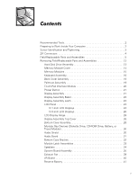
Parts and Assemblies 12 Hard-Disk Drive Assembly 13 Memory Module Cover 14 Memory Modules 15 Keyboard Assembly 16 Back Cover Assembly 18 Palmrest Assembly 19 Touch-Pad Interface Module 20 Power Button 21 Display Assembly 21 Display Assembly Bezel 23 Display Assembly Latch 23 LCD - Dell Latitude CPi A | User Manual - Page 4
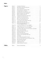
. Figure 30. Figure 31. Computer Orientation 1 Main Battery Assembly Removal 3 Screw Identification 3 Disconnecting an Interface Cable 4 Exploded View-Computer 12 Hard-Disk Drive Assembly Removal 13 Memory Module Cover Removal 14 Memory Module Removal 15 Keyboard Assembly Screw Removal 16 - Dell Latitude CPi A | User Manual - Page 5
vii - Dell Latitude CPi A | User Manual - Page 6
this manual to service Dell computer systems is a basic knowledge of IBM-compatible PCs and prior training in IBM-compatible PC troubleshooting techniques. In addition to information provided in this manual, Dell provides the System Users Guide for troubleshooting procedures and instructions on - Dell Latitude CPi A | User Manual - Page 7
never be allowed to exceed 180 degrees. Also, when performing the procedures in this manual, the locations or directions relative to the computer are as shown in Figure 1 unless otherwise specified. back of computer left side right side front of computer Dell Latitude CPi A Service Manual 1 - Dell Latitude CPi A | User Manual - Page 8
and any attached peripherals from AC power sources to reduce the Cards. 8. Remove the main battery assembly from the battery bay. Slide the battery bay latch away from the center of the computer. Then slide the battery out of the battery bay (see Figure 2). 2 Dell Latitude CPi A Service Manual - Dell Latitude CPi A | User Manual - Page 9
also included in the illustration. Examples are shown in Figure 3. Match the actual screw to the graphic in the illustration to check for correct length. Dell Latitude CPi A Service Manual 3 - Dell Latitude CPi A | User Manual - Page 10
into the connector. 3. While holding the cable in place, close the ZIF connector. To ensure a firm connection, make sure the ZIF connector is completely closed. 4 Dell Latitude CPi A Service Manual - Dell Latitude CPi A | User Manual - Page 11
BTRY,MN,14.4V,8CELL,LITH Service kit, reserve battery Reserve battery Reserve battery sponge pad SVC,BTRY,RSRV,7.2V,30MAH,6, NIHD BTRY,RSRV,7.2V,30MAH,6, NIHD PAD,FOAM,BRTY,RSRV,CPi A Bottom case assembly ASSY,CVR,BTM,PLSTC, BASE,CPi A 22 22 11 2 31 5, 26 Dell Latitude CPi A Service Manual 5 - Dell Latitude CPi A | User Manual - Page 12
shield SVC,SUBASSY,FD,F3, INT/EXT,CPi A SUBASSY,FD,F3,INT/EXT,CPi A FD,F3,CPi A CVR,BTM,PLSTC,FD,F3,CPi A CVR,TOP,PLSTC,FD,F3,CPi A PWA,INTFC,FD,F3,CPi A CBL,FPC,FD,F3,CPi A SHLD,FD,F3,CPi A Service kit, exhaust fan SVC,FAN,25X25X10,CPi A 20, 23 21 21 29 6 Dell Latitude CPi A Service Manual - Dell Latitude CPi A | User Manual - Page 13
, Korean KYBD,87,KOR,CPi A Keyboard, Latin American KYBD,88,LAC,CPi A Keyboard, Norwegian KYBD,88,NOR,CPi A Keyboard, Portuguese KYBD,88,PORTUGEUSE,CPi A * Substitute the drive capacity for xxxxx, the drive height for yy, and the manufacturer for zzz. Dell Latitude CPi A Service Manual 7 - Dell Latitude CPi A | User Manual - Page 14
service kit, SVC,LCD/CBL/INV,TFT,zzz,13.3", including LCD, brackets, cable, CPi A* inverter, and bezel 18, 19 Latch service kit SVC,LATCH,DIS,BZL,CPi A * Substitute the drive capacity for xxxxx, the drive height for yy, and the manufacturer for zzz. 14, 15 8 Dell Latitude CPi A Service Manual - Dell Latitude CPi A | User Manual - Page 15
-pad bracket Air flow duct BRCKT,TPAD,CPi A 13 GDE,INTK,AIR,FAN,PLSTC,CPi A 26 Service kit, palmrest assembly SVC,SUBASSY,PLMRST,CPi A 12 Palmrest assembly ASSY,PLMRST,GRY,CPi A Power button SWT,PWR SW, CPi A Power button spring SPR,PWR SW,CPi A Dell Latitude CPi A Service Manual 9 - Dell Latitude CPi A | User Manual - Page 16
, CPi A, SVC,ASSY,PRM/PWA,ENGINE,CPi A service kit Service tag installation diskette DSK,BIOS,FLDSVC,F3,US,CP BIOS flash diskette KIT,BIOS,FLASH,UPG,F3,CP Diagnostic diskette KIT,DSK,DIAG,F3,CPi A,WW System board assembly ASSY,PRM/PWA,ENGINE, CPi A 10 Dell Latitude CPi A Service Manual - Dell Latitude CPi A | User Manual - Page 17
,CPi A FAN,25X25X10,CPi A MCPHN,CPi A BTRY,RSRV,7.2,30MAH,6,NIHD PAD,FOAM,BTRY,RSRV,CPi A Service kit, thermal cooling SVC,SUBASSY,HTSNK, 26 subassembly CPU,HYB,CPi A Touch-pad service kit SVC,TPAD,SQ,INTFC,CPi A 13 Touch-pad subassembly TPA,INTFC,CPi A Dell Latitude CPi A Service Manual - Dell Latitude CPi A | User Manual - Page 18
display assembly keyboard palmrest assembly main battery back cover assembly modular bay device bottom case assembly The following subsections provide instructions for removing and replacing field-replaceable parts and assemblies. 12 Dell Latitude CPi A Service Manual - Dell Latitude CPi A | User Manual - Page 19
5-mm screws (2) hard-disk drive door 1. Turn the computer over, and remove the two 5-mm screws from the hard-disk drive door. The drive is on the left side of the computer. 2. Grasp the drive door and pull the drive out of the computer. Dell Latitude CPi A Service Manual 13 - Dell Latitude CPi A | User Manual - Page 20
turn the computer upside down on a flat work surface. 2. Release the memory module cover. Insert a fingertip in the indentation in the bottom case assembly and lift the cover slightly; then slide the cover in the direction indicated by the arrow on the cover. 14 Dell Latitude CPi A Service Manual - Dell Latitude CPi A | User Manual - Page 21
. 4. Lift the memory module out of its socket. You can install memory modules only one way. Do not attempt to force the memory module into the socket. Align the notch near the center of the memory module with the corresponding key in the memory module socket. Dell Latitude CPi A Service Manual 15 - Dell Latitude CPi A | User Manual - Page 22
12-mm screws securing the keyboard to the computer. 3. Turn the computer right-side up and open the display. 4. Release the keyboard from the palmrest assembly: a. Carefully deflect the palmrest (next to the blank key and lift the right edge of the keyboard. 16 Dell Latitude CPi A Service Manual - Dell Latitude CPi A | User Manual - Page 23
the keyboard is correctly installed. The keys should be flush with the left and right surfaces of the palmrest. 5. Reinstall the six 12-mm screws. Dell Latitude CPi A Service Manual 17 - Dell Latitude CPi A | User Manual - Page 24
5-mm screws (12) 1. Close the display. 2. Remove the twelve 5-mm screws securing the back cover: Five screws on the underside of the back cover One cover assembly firmly, and unsnap it from the computer. Then disengage the left end of the back cover assembly. 18 Dell Latitude CPi A Service Manual - Dell Latitude CPi A | User Manual - Page 25
mm screw inside the computer, adjacent to the thermal cooling assembly. Two 5-mm screws inside the upper edge of the hard-disk drive bay. (You must remove the hard-disk drive to access these screws.) Three 12-mm screws underneath the front edge of the computer. Dell Latitude CPi A Service Manual 19 - Dell Latitude CPi A | User Manual - Page 26
up on the work surface, and open the display assembly 180 degrees. NOTE: Support the display assembly with a book or similar object so that the display assembly does not open beyond 180 degrees. . 3. Remove the four 1.8-mm screws securing the touch-pad bracket. 20 Dell Latitude CPi A Service Manual - Dell Latitude CPi A | User Manual - Page 27
Compress the two catches securing the power button, and remove the power button and spring from the palmrest assembly. display assembly black 5-mm displayassembly interfacecable grounding screws (2) display-assembly interface cable 5-mm screws (4) hinges (2) Dell Latitude CPi A Service Manual 21 - Dell Latitude CPi A | User Manual - Page 28
two hinge brackets to the bottom case assembly. 8. Lift the display assembly from the bottom case assembly. NOTE: When you reinstall the display assembly, install the four screws securing the hinges at the locations marked by arrows on the face of each hinge. 22 Dell Latitude CPi A Service Manual - Dell Latitude CPi A | User Manual - Page 29
, you must remove the LCD panel before you can remove the display assembly latch. 1. Remove the display assembly bezel. 2. Remove the display assembly latch by unsnapping the latch and captive spring from the inside of the display assembly top-cover assembly. Dell Latitude CPi A Service Manual 23 - Dell Latitude CPi A | User Manual - Page 30
the display assembly bezel. 5. Remove the two 4.5-mm screws at the right corners of the LCD panel. 6. Remove the two screws holding the interface connector. 7. Disconnect the interface connector. Figure 17 shows the cable layout for a 12.1-inch LCD panel. 24 Dell Latitude CPi A Service Manual - Dell Latitude CPi A | User Manual - Page 31
8. Use the yellow tab to lift the right side of the LCD panel, slide the LCD panel to the right, and then lift the LCD panel out of the top cover. NOTE: Remove and replace the LCD as a whole assembly. inverter connector LCD connector interface connector Dell Latitude CPi A Service Manual 25 - Dell Latitude CPi A | User Manual - Page 32
top cover LCD inverter board LCD panel power cable 1. Remove the display assembly bezel. 2. Remove the two 4.5-mm screws at the right corners of the LCD panel. 3. connector. Figure 19 shows the two-piece (A and B) cable layout for a 13.3-inch LCD panel. 26 Dell Latitude CPi A Service Manual - Dell Latitude CPi A | User Manual - Page 33
to replace the bottom LCD cable on the 12.1-inch display, use two bends to route the new cable to the inverter board connector. LCD B cable (stays with LCD panel) connector tape center-junction connector inverter connector LCD A cable interface connector Dell Latitude CPi A Service Manual 27 - Dell Latitude CPi A | User Manual - Page 34
assembly, CD-ROM drive assembly, or travel module) Back cover assembly Audio shield Audio board Bottom case bracket Module latch assemblies Speakers System board assembly Thermal cooling assembly Air flow duct Exhaust fan Infrared (I/R) board Reserve battery 28 Dell Latitude CPi A Service Manual - Dell Latitude CPi A | User Manual - Page 35
audio shield thermal cooling assembly I/R board system board assembly bottom case bracket module latch assembly (2) main battery audio board air flow duct exhaust fan modular bay device speakers (2) Dell Latitude CPi A Service Manual 29 - Dell Latitude CPi A | User Manual - Page 36
latch lock NOTE: You do not need to remove the main battery or hard-disk drive prior to this procedure. 1. Close the display and turn the computer over. 2. Remove the device from the modular device in the modular bay prior to reinstalling the palmrest assembly.) 30 Dell Latitude CPi A Service Manual - Dell Latitude CPi A | User Manual - Page 37
with devices installed in the modular bay. (You can check this by temporarily installing a device in the modular bay prior to reinstalling the palmrest assembly.) Dell Latitude CPi A Service Manual 31 - Dell Latitude CPi A | User Manual - Page 38
the right side of the bottom case bracket. 8. Insert the end of a small flat-blade screwdriver into the slot in the vertical support in the center of the bottom case, and disengage the plastic retaining clip. 9. Lift the bottom case bracket from the computer. 32 Dell Latitude CPi A Service Manual - Dell Latitude CPi A | User Manual - Page 39
reinsert the spring onto the plunger on the slider, and reinstall the slider-spring assembly into the holding features on the inside of the case. Dell Latitude CPi A Service Manual 33 - Dell Latitude CPi A | User Manual - Page 40
the bottom case so that the speaker wires are facing upwards. Route the speaker wires under their retaining clips on the bottom case bracket. 34 Dell Latitude CPi A Service Manual - Dell Latitude CPi A | User Manual - Page 41
board's basic input/output system (BIOS) chip contains the system service tag number, which is also service tag number to the replacement system board assembly. 1. Remove the back cover assembly. 2. Remove the keyboard assembly. 3. Remove the palmrest assembly. Dell Latitude CPi A Service Manual - Dell Latitude CPi A | User Manual - Page 42
a two-slot hold-down clip (see Figure 27), repeat substeps a and b for the second slot . d. Lift the clip off the fence and discard it. 36 Dell Latitude CPi A Service Manual - Dell Latitude CPi A | User Manual - Page 43
processor module. The tool fits on the left side of the module, in the notches. 9. Remove the air flow duct. 10. Verify that the PC Card ejectors do not extend from the PC Card bay. 11. Remove the 2.5-mm screw from the center of the computer's left rear foot. Dell Latitude CPi A Service Manual 37 - Dell Latitude CPi A | User Manual - Page 44
service tag number into the BIOS of the replacement system board assembly. Insert the diskette that accompanied the replacement system board assembly into the diskette drive, and turn on the computer. Follow the instructions on the display -module fence holes 38 Dell Latitude CPi A Service Manual - Dell Latitude CPi A | User Manual - Page 45
). (This prevents the fan wires from being pinched when you reassemble the computer.) Make sure that the wires are routed under the upper EMI shield. Dell Latitude CPi A Service Manual 39 - Dell Latitude CPi A | User Manual - Page 46
5-mm screw I/R board 1. Remove the palmrest assembly. 2. Remove the 5-mm screw securing the I/R board to the system board assembly. 3. Lift the I/R board straight up from the system board assembly. 40 Dell Latitude CPi A Service Manual - Dell Latitude CPi A | User Manual - Page 47
of the foam pad from the system board assembly. NOTE: When you replace the reserve battery, first connect the reserve battery cable to the system board. Then position the reserve battery on the hard-disk drive bay so that there is minimal slack in the cable. Dell Latitude CPi A Service Manual 41 - Dell Latitude CPi A | User Manual - Page 48
42 Dell Latitude CPi A Service Manual - Dell Latitude CPi A | User Manual - Page 49
31 audio shield removal, 30 back cover assembly removal, 18 battery (in modular bay) removal, 30 bottom case assembly components, 28 illustrated, 29 bottom case bracket removal, 32 CD-ROM drive removal, 30 diskette drive removal, 30 display assembly bezel, removal, 23 removal, 21 top cover, removal - Dell Latitude CPi A | User Manual - Page 50
, 3 sockets memory module, 15 speakers removal, 34 system board assembly removal, 35 tools, 2 touch-pad interface module removal, 20 travel module removal, 30 palmrest assembly removal, 19 power button removal, 21 preparing to work, 2 ZIF connectors, 4 2 Dell Latitude CPi A Service Manual
-
 1
1 -
 2
2 -
 3
3 -
 4
4 -
 5
5 -
 6
6 -
 7
7 -
8
-
9
-
10
-
11
-
12
-
13
-
14
-
15
-
16
-
17
-
18
-
19
-
20
-
21
-
22
-
23
-
24
-
25
-
26
-
27
-
28
-
29
-
30
-
31
-
32
-
33
-
34
-
35
-
36
-
37
-
38
-
39
-
40
-
41
-
42
-
43
-
44
-
45
-
46
-
47
-
48
-
49
-
50
 |
 |
±±±²³´µµ²¶·¸
±
±²³³´µ¶·¸¹¸º»²´µ¼½¹µ¾
±²³´µ¶²·¸¹º»¹¼