Dell Latitude CPi A User Manual - Page 26
Touch-Pad Interface Module, the snaps when removing the palmrest.
 |
View all Dell Latitude CPi A manuals
Add to My Manuals
Save this manual to your list of manuals |
Page 26 highlights
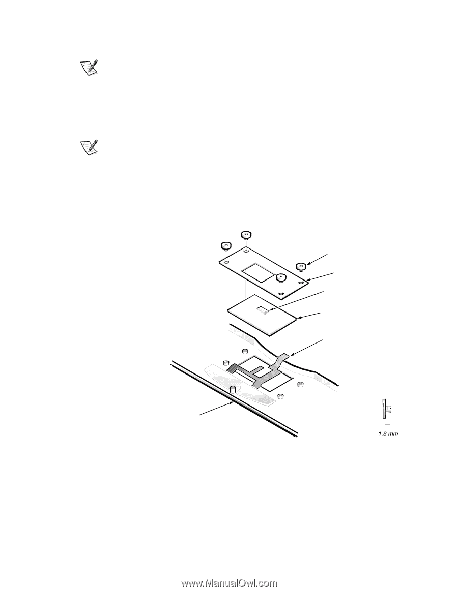
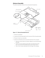
5. Turn the computer right-side up on the work surface, and open the display assembly 180 degrees. NOTE: Support the display assembly with a book or similar object so that the display assembly does not open beyond 180 degrees. 6. Carefully remove the palmrest assembly from the bottom case assembly. The palmrest assembly is secured in the bottom case assembly by four snaps and tabs on the right and left ends of the palmrest. Take care not to damage the snaps when removing the palmrest. NOTE: When you replace the palmrest, ensure that the vertical tab at the back of the palmrest fits on the outside of the system board assembly, near the parallel port connector. Also, check that the microphone boot is properly located in its slot on the top electromagnetic interference (EMI) shield and is fitted within the palmrest assembly. 1.8-mm screws (4) touch-pad bracket interface connector J1 touch-pad interface module touch-pad cable palmrest assembly 1. Remove the palmrest assembly. 2. Turn the palmrest assembly upside down on a flat work surface. 3. Remove the four 1.8-mm screws securing the touch-pad bracket. 20 Dell Latitude CPi A Service Manual
-
 1
1 -
2
-
3
-
4
-
5
-
6
-
7
-
8
-
9
-
10
-
11
-
12
-
13
-
14
-
15
-
16
-
17
-
18
-
19
-
20
-
 21
21 -
 22
22 -
 23
23 -
 24
24 -
 25
25 -
 26
26 -
 27
27 -
 28
28 -
 29
29 -
 30
30 -
 31
31 -
32
-
33
-
34
-
35
-
36
-
37
-
38
-
39
-
40
-
41
-
42
-
43
-
44
-
45
-
46
-
47
-
48
-
49
-
50
 |
 |