Dell Latitude CPi A User Manual - Page 25
Palmrest Assembly, Two 5-mm screws inside the upper edge of the hard-disk drive bay.
 |
View all Dell Latitude CPi A manuals
Add to My Manuals
Save this manual to your list of manuals |
Page 25 highlights
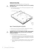
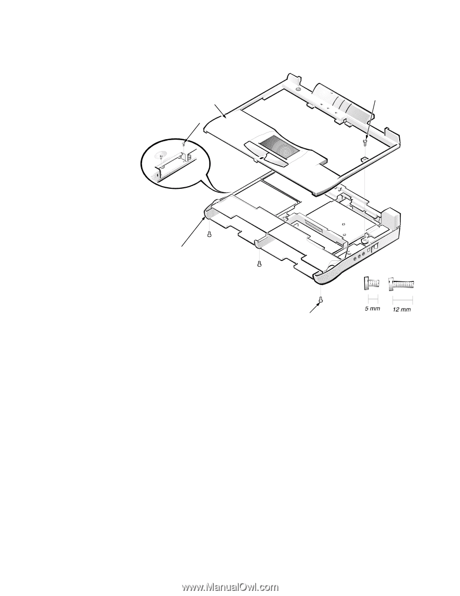
The palmrest assembly consists of the touch pad and the palmrest. palmrest assembly 5-mm screws (2) 5-mm screw bottom case assembly 12-mm screws (3) 1. Remove the keyboard. 2. Disconnect the touch-pad cable from ZIF connector JP2 on the system board. 3. Remove the back cover assembly. 4. Remove the following screws securing the palmrest to the computer: One 5-mm screw inside the computer, adjacent to the thermal cooling assembly. Two 5-mm screws inside the upper edge of the hard-disk drive bay. (You must remove the hard-disk drive to access these screws.) Three 12-mm screws underneath the front edge of the computer. Dell Latitude CPi A Service Manual 19
-
 1
1 -
2
-
3
-
4
-
5
-
6
-
7
-
8
-
9
-
10
-
11
-
12
-
13
-
14
-
15
-
16
-
17
-
18
-
19
-
 20
20 -
 21
21 -
 22
22 -
 23
23 -
 24
24 -
 25
25 -
 26
26 -
 27
27 -
 28
28 -
 29
29 -
 30
30 -
31
-
32
-
33
-
34
-
35
-
36
-
37
-
38
-
39
-
40
-
41
-
42
-
43
-
44
-
45
-
46
-
47
-
48
-
49
-
50
 |
 |
Dell Latitude CPi A Service Manual
19
ɲÀ¾³¼¸Êº½¸¸¼¾¿ÀÁ
The palmrest assembly consists of the touch pad and the palmrest.
±²³´µ¶·¸Â¹··&Áɼµ¶Ç¾·ÆÇǶ¼ÈÉŷʶ¼»ËÁÉ···
1.
Remove the keyboard.
2.
Disconnect the touch-pad cable from ZIF connector JP2 on the system board.
3.
Remove the back cover assembly.
4.
Remove the following screws securing the palmrest to the computer:
±
One 5-mm screw inside the computer, adjacent to the thermal cooling
assembly.
±
Two 5-mm screws inside the upper edge of the hard-disk drive bay.
(You must remove the hard-disk drive to access these screws.)
±
Three 12-mm screws underneath the front edge of the computer.
palmrest assembly
bottom
case assembly
12-mm screws (3)
5-mm screws (2)
5-mm screw