Dell Latitude CPi A User Manual - Page 32
-Inch LCD Displays, Disconnect the interface cable at the center-junction connector.
 |
View all Dell Latitude CPi A manuals
Add to My Manuals
Save this manual to your list of manuals |
Page 32 highlights
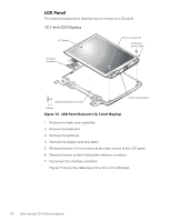
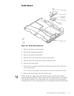
LCD panel interface cable 4.5-mm screws (2) display-assembly top cover LCD inverter board LCD panel power cable 1. Remove the display assembly bezel. 2. Remove the two 4.5-mm screws at the right corners of the LCD panel. 3. Use the yellow tab to lift the right side of the LCD panel, slide the LCD panel to the right, and then pivot the panel up. 4. Remove the connector tape from the interface cable at the center-junction connector on the back of the LCD panel (see Figure 19). 5. Disconnect the interface cable at the center-junction connector. Figure 19 shows the two-piece (A and B) cable layout for a 13.3-inch LCD panel. 26 Dell Latitude CPi A Service Manual
-
 1
1 -
2
-
3
-
4
-
5
-
6
-
7
-
8
-
9
-
10
-
11
-
12
-
13
-
14
-
15
-
16
-
17
-
18
-
19
-
20
-
21
-
22
-
23
-
24
-
25
-
26
-
 27
27 -
 28
28 -
 29
29 -
 30
30 -
 31
31 -
 32
32 -
 33
33 -
 34
34 -
 35
35 -
 36
36 -
 37
37 -
38
-
39
-
40
-
41
-
42
-
43
-
44
-
45
-
46
-
47
-
48
-
49
-
50
 |
 |

26
Dell Latitude CPi A Service Manual
±Â³Â´µ¶·¸ ¹º» »¼½¾¿ÀÁ½
±²³´µ¶·¸1¹··9º$·&ÁÀ¶É·Ê¶¼»ËÁÉ·7¸Ì¹Ì.°ÀÎ5·$²Ç½ÉÁÅ8·
1.
Remove the display assembly bezel.
2.
Remove the two 4.5-mm screws at the right corners of the LCD panel.
3.
Use the yellow tab to lift the right side of the LCD panel, slide the LCD panel
to the right, and then pivot the panel up.
4.
Remove the connector tape from the interface cable at the center-junction
connector on the back of the LCD panel (see Figure 19).
5.
Disconnect the interface cable at the center-junction connector.
±²³´µ¶·¸ ±½Â¿ÉËÅÅÊ Ã¿ÀÀ »ÄȺ ĺ ¾Á¿ Åļ$¹ºÇ ¾½ÍÀ ½º» ¾Á¿º ÃËÅÅ ¾Á¿
¼Äºº¿¼¾Ä ½Ã½Â¾Î
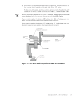
Figure 19 shows the two-piece (A and B) cable layout for a 13.3-inch LCD
panel.
LCD panel
LCD panel
power cable
LCD inverter board
display-assembly top cover
interface cable
4.5-mm screws (2)