Dell Latitude CPi A User Manual - Page 42
Bend the tab away from the fence by carefully tipping the screwdriver, clip see
 |
View all Dell Latitude CPi A manuals
Add to My Manuals
Save this manual to your list of manuals |
Page 42 highlights
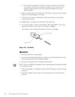
4. Remove the two 3.5-mm screws securing the TCA to the microprocessor module. 5. Remove the TCA from the microprocessor module. 6. If a processor hold-down clip is attached to the processor module fence, remove the clip. Your computer may have a one- or two-slot hold-down clip. One tab locks the one-slot hold-down clip to the fence. Two tabs lock the two-slot clip to the fence. To remove the clip, perform the following steps to bend the tabs away from the fence: a. Insert a small flat-blade screwdriver into one of the slots at the top of the clip (see Figure 27). b. Bend the tab away from the fence by carefully tipping the screwdriver away from the processor module. c. If your computer has a two-slot hold-down clip (see Figure 27), repeat substeps a and b for the second slot . d. Lift the clip off the fence and discard it. 36 Dell Latitude CPi A Service Manual
-
 1
1 -
2
-
3
-
4
-
5
-
6
-
7
-
8
-
9
-
10
-
11
-
12
-
13
-
14
-
15
-
16
-
17
-
18
-
19
-
20
-
21
-
22
-
23
-
24
-
25
-
26
-
27
-
28
-
29
-
30
-
31
-
32
-
33
-
34
-
35
-
36
-
 37
37 -
 38
38 -
 39
39 -
 40
40 -
 41
41 -
 42
42 -
 43
43 -
 44
44 -
 45
45 -
 46
46 -
 47
47 -
48
-
49
-
50
 |
 |