Dell Latitude CPi A User Manual - Page 27
Power Button, Display Assembly, Turn the palmrest assembly upside down on a flat work surface.
 |
View all Dell Latitude CPi A manuals
Add to My Manuals
Save this manual to your list of manuals |
Page 27 highlights
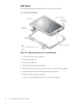
4. Carefully disconnect the touch-pad cable from ZIF connector J1 on the touch-pad interface module. To release the ZIF connector latch, use a fingernail to lift up the central portion of the black plastic latch. 5. Remove the touch-pad interface module from the palmrest. 1. Remove the palmrest assembly. 2. Turn the palmrest assembly upside down on a flat work surface. 3. Compress the two catches securing the power button, and remove the power button and spring from the palmrest assembly. display assembly black 5-mm displayassembly interfacecable grounding screws (2) display-assembly interface cable 5-mm screws (4) hinges (2) Dell Latitude CPi A Service Manual 21
-
 1
1 -
2
-
3
-
4
-
5
-
6
-
7
-
8
-
9
-
10
-
11
-
12
-
13
-
14
-
15
-
16
-
17
-
18
-
19
-
20
-
21
-
 22
22 -
 23
23 -
 24
24 -
 25
25 -
 26
26 -
 27
27 -
 28
28 -
 29
29 -
 30
30 -
 31
31 -
 32
32 -
33
-
34
-
35
-
36
-
37
-
38
-
39
-
40
-
41
-
42
-
43
-
44
-
45
-
46
-
47
-
48
-
49
-
50
 |
 |

Dell Latitude CPi A Service Manual
21
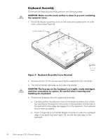
4.
Carefully disconnect the touch-pad cable from ZIF connector J1 on the
touch-pad interface module.
To release the ZIF connector latch, use a fingernail to lift up the central portion
of the black plastic latch.
5.
Remove the touch-pad interface module from the palmrest.
É𼳺ÇÄÊÊÃκººº
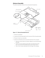
1.
Remove the palmrest assembly.
2.
Turn the palmrest assembly upside down on a flat work surface.
3.
Compress the two catches securing the power button, and remove the
power button and spring from the palmrest assembly.
¶·¸!À²Áº½¸¸¼¾¿ÀÁ
±²³´µ¶·¸#¹··$²Ç½ÉÁÅ·ÆÇǶ¼ÈÉŷʶ¼»ËÁÉ
display-assembly
interface cable
display assembly
hinges (2)
5-mm screws (4)
black 5-mm display-
assembly interface-
cable grounding
screws (2)