Dell Latitude CPi A User Manual - Page 30
LCD Panel, 12.1-Inch LCD Displays, Remove the two screws holding the interface connector.
 |
View all Dell Latitude CPi A manuals
Add to My Manuals
Save this manual to your list of manuals |
Page 30 highlights
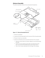
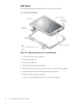
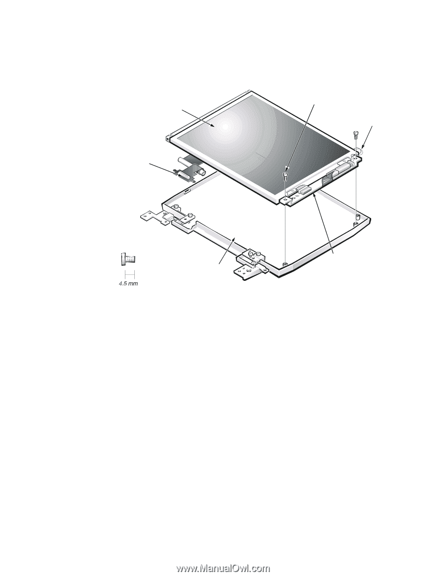
The following subsections describe how to remove an LCD panel. LCD panel interface connector 4.5-mm screws (2) LCD panel power cable display-assembly top cover LCD inverter board 1. Remove the back cover assembly. 2. Remove the keyboard. 3. Remove the palmrest. 4. Remove the display assembly bezel. 5. Remove the two 4.5-mm screws at the right corners of the LCD panel. 6. Remove the two screws holding the interface connector. 7. Disconnect the interface connector. Figure 17 shows the cable layout for a 12.1-inch LCD panel. 24 Dell Latitude CPi A Service Manual
-
 1
1 -
2
-
3
-
4
-
5
-
6
-
7
-
8
-
9
-
10
-
11
-
12
-
13
-
14
-
15
-
16
-
17
-
18
-
19
-
20
-
21
-
22
-
23
-
24
-
 25
25 -
 26
26 -
 27
27 -
 28
28 -
 29
29 -
 30
30 -
 31
31 -
 32
32 -
 33
33 -
 34
34 -
 35
35 -
36
-
37
-
38
-
39
-
40
-
41
-
42
-
43
-
44
-
45
-
46
-
47
-
48
-
49
-
50
 |
 |
24
Dell Latitude CPi A Service Manual
#ŶºÉ²Î¼Àººº
The following subsections describe how to remove an LCD panel.
±²³±´µ¶·¸ ¹º» »¼½¾¿ÀÁ½
±²³´µ¶·¸,¹··9º$·&ÁÀ¶É·Ê¶¼»ËÁÉ·7¸Â¹¸.°ÀÎ5·$²Ç½ÉÁÅ8·
1.
Remove the back cover assembly.
2.
Remove the keyboard.
3.
Remove the palmrest.
4.
Remove the display assembly bezel.
5.
Remove the two 4.5-mm screws at the right corners of the LCD panel.
6.
Remove the two screws holding the interface connector.
7.
Disconnect the interface connector.
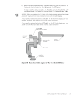
Figure 17 shows the cable layout for a 12.1-inch LCD panel.
LCD panel
LCD panel
power cable
LCD inverter board
display-assembly top cover
interface
connector
4.5-mm screws (2)