Dell M4400 Service Manual
Dell M4400 - Precision Mobile Workstation Manual
 |
View all Dell M4400 manuals
Add to My Manuals
Save this manual to your list of manuals |
Dell M4400 manual content summary:
- Dell M4400 | Service Manual - Page 1
Dell Precision™ Mobile Workstation M4400 Service Manual Troubleshooting Before Working on Your Computer Base Assembly Hinge Covers Hard Drive WLAN Card WWAN Card WPAN/UWB Card Fan Heat Sinks Processor Module Memory Coin-Cell Battery Modular Drive LED Cover Keyboard Right Speaker Grill and - Dell M4400 | Service Manual - Page 2
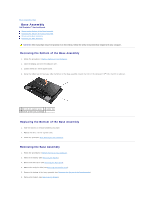
Page Base Assembly Dell Precision™ Service Manual Removing the Bottom of the Base Assembly Replacing the Bottom of the Base Assembly Removing the Base Assembly Replacing the Base Assembly CAUTION: Before you begin any of the procedures in this section, follow the safety instructions that shipped - Dell M4400 | Service Manual - Page 3
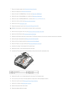
tab 2 PC card cage 4 plastic scribe 24. Remove the five M2.5 x 5-mm screws labeled with white arrows from the system board. 25. Pull out on the top, left corner of the base assembly to release the DC, USB, and display connectors. 26. Remove the system board (see Removing the System Board Assembly - Dell M4400 | Service Manual - Page 4
(see Replacing the Bottom of the Base Assembly). 22. Replace the modular drive (see Replacing the Modular Drive). 23. Replace the hard drive (see Replacing the Hard Drive). 24. Replace the battery (see Replacing the Battery). 25. Follow the procedure After Working on Your Computer. Back to Contents - Dell M4400 | Service Manual - Page 5
system components may appear differently than shown in this document. Recommended Tools The procedures in this document may require the following tools: l Small flat-blade screwdriver l Phillips #0 screwdriver l Small plastic scribe l Flash BIOS update (see the Dell Support website at support.dell - Dell M4400 | Service Manual - Page 6
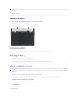
into the battery bay until it clicks into place. 2. Turn the computer top-side up, open the display, and press the power button to ground the system board. After Working on Your Computer After you have completed the replacement procedures, ensure you connect the external devices, cards, cables, and - Dell M4400 | Service Manual - Page 7
do so may cause system damage. 1. Ensure that the DC adapter is plugged in, the main battery is properly installed, and a network cable is attached. 2. Turn on the computer. 3. Locate the latest BIOS update file for your computer at support.dell.com. 4. Click Download Now to download the file. 5. If - Dell M4400 | Service Manual - Page 8
Back to Contents Page Express Card Cage Dell Precision™ Service Manual Removing the Express Card Cage Replacing the Express Card Cage Removing the Express Card Cage CAUTION: Before you begin any of the procedures in this section, follow the safety instructions that shipped with your computer. 1. - Dell M4400 | Service Manual - Page 9
the Keyboard). 6. Replace the display assembly (see Replacing the Display Assembly). 7. Replace the bottom of the base assembly (see Replacing the Bottom of the Base Assembly). 8. Replace the modular drive (see Replacing the Modular Drive). 9. Replace the hard drive (see Replacing the Hard Drive - Dell M4400 | Service Manual - Page 10
Back to Contents Page Coin-Cell Battery Dell Precision™ Service Manual Removing the Coin-Cell Battery Replacing the Coin-Cell Battery Removing the Coin-Cell Battery CAUTION: Before you begin any of the procedures in this section, follow the safety instructions that shipped with your computer. NOTICE - Dell M4400 | Service Manual - Page 11
- Dell M4400 | Service Manual - Page 12
information, see the Regulatory Compliance Homepage on www.dell.com at: www.dell.com/regulatory_compliance. 1. Follow the instructions in Before Working on Your Computer. 2. Remove the bottom of the base assembly (see Removing the Bottom of the Base Assembly). 3. Remove the fan (see Removing the Fan - Dell M4400 | Service Manual - Page 13
intermittent connection or system board. 3. Replace the processor heat sink (see Replacing the Discrete Graphics Heat Sink). 4. Replace the fan (see Replacing the Fan). 5. Replace the bottom of the base assembly (see Removing the Bottom of the Base Assembly). 6. Follow the procedure After Working - Dell M4400 | Service Manual - Page 14
the processor heat sink, complete the following steps: 1. Follow the instructions in Before Working on Your Computer. 2. Close the display and turn the computer over. 3. Remove the bottom of the base assembly (see Removing the Bottom of the Base Assembly). 4. Remove the fan (see Removing the Fan - Dell M4400 | Service Manual - Page 15
the Regulatory Compliance Homepage on www.dell.com at: www.dell.com/regulatory_compliance. Before installing the system board. 3. Replace the fan (see Replacing the Fan). 4. Replace the bottom of the base assembly (see Removing the Bottom of the Base Assembly). 5. Follow the procedure After Working - Dell M4400 | Service Manual - Page 16
Contents Page I/O Board Dell Precision™ Service Manual Removing the I/O Board Replacing the I/O Board Removing the I/O Board CAUTION: Before you begin the following procedure, follow the safety instructions that shipped with your computer. 1. Follow the procedures in Before Working on Your Computer - Dell M4400 | Service Manual - Page 17
Back to Contents Page - Dell M4400 | Service Manual - Page 18
to Contents Page Display Assembly Dell Precision™ Service Manual Removing the Display Assembly Replacing the Display Assembly Removing the Display Bezel Replacing the Display Bezel Removing the Display Panel Replacing the Display Panel Display Inverter Removing the Camera and Microphone Assembly - Dell M4400 | Service Manual - Page 19
card slot. 8. Connect the display cable to the display cable connector on the system board. 9. Replace the hinge covers (see Replacing the Hinge Covers). 10. Replace the bottom of the base assembly (see Replacing the Bottom of the Base Assembly). 11. Replace the battery (see Replacing the Battery - Dell M4400 | Service Manual - Page 20
the bezel into place to secure it to the display panel. 3. Replace the display assembly (see Replacing the Display Assembly). Removing the Display Panel The Dell Precision M4400 laptop includes either a CCFL display panel or an LED display panel. Use the procedure applicable to the configuration of - Dell M4400 | Service Manual - Page 21
Regulatory Compliance Homepage on www.dell.com at: www.dell.com/regulatory_compliance. 1. Follow the instructions in Before Working on Your Computer. 2. Remove the display assembly (see Removing the Display Assembly). 3. Remove the display bezel (see Removing the Display Bezel). 4. Remove the four - Dell M4400 | Service Manual - Page 22
7. Remove the two M2 x 3-mm screws from both the right and left display panel brackets, then remove the brackets. Replacing the Display Panel The Dell Precision M4400 laptop includes either a CCFL display panel or an LED display panel. Use the procedure applicable to the configuration of the - Dell M4400 | Service Manual - Page 23
the Regulatory Compliance Homepage on www.dell.com at: www.dell.com/regulatory_compliance. 1. Follow the instructions in Before Working on Your Computer. 2. Remove the display assembly (see Removing the Display Assembly). 3. Remove the display bezel (see Removing the Display Bezel). 4. Remove the M2 - Dell M4400 | Service Manual - Page 24
at: www.dell.com/regulatory_compliance. 1. Follow the instructions in Before Working on Your Computer. 2. Remove the display assembly (see Removing the Display Assembly). 3. Remove the display bezel (see Removing the Display Bezel). 4. Lift the small connector lever on the camera/microphone cable - Dell M4400 | Service Manual - Page 25
the Regulatory Compliance Homepage on www.dell.com at: www.dell.com/regulatory_compliance. 1. Follow the instructions in Before Working on Your Computer. 2. Remove the display assembly (see Removing the Display Assembly). 3. Remove the display bezel (see Removing the Display Bezel). 4. Remove the M2 - Dell M4400 | Service Manual - Page 26
see the Regulatory Compliance Homepage on www.dell.com at: www.dell.com/regulatory_compliance. NOTICE: Position all display assembly cables toward the back, away from the base assembly before installing the display assembly. 1. Follow the instructions in Before Working on Your Computer 2. Remove the - Dell M4400 | Service Manual - Page 27
7. Replace the bottom of the base assembly (see Replacing the Bottom of the Base Assembly). 8. Follow the procedure After Working on Your Computer. Back to Contents Page - Dell M4400 | Service Manual - Page 28
Dell Precision™ Service Manual Removing the Fan Replacing the Fan Removing the Fan CAUTION: Before working dell.com at: www.dell.com/regulatory_compliance. 1. Follow the instructions in Before Working on Your Computer. 2. Close the display and turn the computer over. 3. Remove the bottom of the base - Dell M4400 | Service Manual - Page 29
- Dell M4400 | Service Manual - Page 30
or WPAN Mini-Card slot. NOTE: This card is only compatible with the Windows Vista® operating system. If you ordered an FCM with your computer, the card is already installed. Removing an FCM 1. Follow the procedures in Before Working on Your Computer. 2. Remove the bottom of the base assembly (see - Dell M4400 | Service Manual - Page 31
/FCM silk-screened inside the slot. Do not install an FCM in any other Mini-Card slot. 1. Slide the FCM into the connector at a 30-degree angle to the system board. 2. Press the module down onto the alignment post and hold in position. 3. Replace the screw to secure the FCM to the base assembly - Dell M4400 | Service Manual - Page 32
Back to Contents Page Hard Drive Dell Precision™ Service Manual Removing the Hard Drive Replacing the Hard Drive NOTE: Dell does not guarantee compatibility or provide support for hard drives obtained from sources other than Dell. Removing the Hard Drive CAUTION: Before working inside your computer, - Dell M4400 | Service Manual - Page 33
Working on Your Computer. 6. Start up your computer. 7. If you have installed a new or different hard drive, try to restart your computer. If it doesn't restart: l use your Operating System installation media to install the operating system for your computer (see your Setup and Quick Reference Guide - Dell M4400 | Service Manual - Page 34
Back to Contents Page Hinge Covers Dell Precision™ Service Manual Removing the Hinge Covers Replacing the Hinge Covers Removing the Hinge Covers CAUTION: Before you begin any of the procedures in this section, follow the safety instructions that shipped with your computer. The hinge covers are not - Dell M4400 | Service Manual - Page 35
Contents Page Keyboard Dell Precision™ Service Manual Removing the Keyboard Replacing the Keyboard Removing the Keyboard CAUTION: Before you begin any of the procedures in this section, follow the safety instructions that shipped with your computer. 1. Follow the procedures in Before Working on Your - Dell M4400 | Service Manual - Page 36
1 keyboard connector 2 tabs (5) 3 M2 x 3-mm screw (2) 4. Replace the LED cover (see Replacing the LED Cover). 5. Close the display and turn the computer over. 6. Follow the procedure After Working on Your Computer. Back to Contents Page - Dell M4400 | Service Manual - Page 37
Back to Contents Page LED Cover Dell Precision™ Service Manual Removing the LED Cover Replacing the LED Cover Removing the LED Cover CAUTION: Before you begin any of the procedures in this section, follow the safety instructions that shipped with your computer. 1. Follow the procedures in Before - Dell M4400 | Service Manual - Page 38
Back to Contents Page Memory Dell Precision™ Service Manual Removing a Memory Module Replacing a Memory Module Verifying System Operation CAUTION: Before you begin any of the procedures in this section, follow the safety instructions in the Dell™ Product Information Guide. CAUTION: To avoid - Dell M4400 | Service Manual - Page 39
is the one closest to the system board. If a memory module is installed in the DIMM B socket, it must be removed before a memory module in the DIMM A socket can be replaced. 1. Ground yourself by touching a bare-metal part in the computer chassis. 2. Remove the memory module from its anti-static - Dell M4400 | Service Manual - Page 40
memory and automatically updates the system configuration information. Verify that the memory capacity shown on the display is what is expected. 5. To confirm the amount of memory installed in the computer: ® ® l In the Microsoft Windows Vista operating system, click Start ® Help and Support - Dell M4400 | Service Manual - Page 41
Compliance Homepage on www.dell.com at: www.dell.com/regulatory_compliance. 1. Follow the procedures in Before Working on Your Computer. 2. Close the display and turn the computer over. 3. Remove the battery (see Removing the Battery). 4. Remove the bottom of the base assembly (see Removing the - Dell M4400 | Service Manual - Page 42
6. Follow the procedure After Working on Your Computer. Back to Contents Page - Dell M4400 | Service Manual - Page 43
Back to Contents Page Modular Drive Dell Precision™ Service Manual Removing the Modular Drive Replacing the Modular Drive The modular drive bay supports either a second hard drive, an optical drive, or an air bay for travel. Removing the Modular Drive CAUTION: Before you begin any of the procedures - Dell M4400 | Service Manual - Page 44
.com at: www.dell.com/regulatory_compliance. 1. Follow the instructions in Before Working on Your Computer. 2. Remove the bottom of the base assembly (see Removing the Bottom of the Base Assembly). 3. Remove the hard drive (see Removing the Hard Drive). 4. Remove the modular drive (see Removing the - Dell M4400 | Service Manual - Page 45
wireless catcher cable from the system board. 13. Disconnect the speaker cable from the system board. 14. Use the pull tab to disconnect the touch pad cable from the system Assembly CAUTION: Before working inside your computer, Homepage on www.dell.com at: www.dell.com/regulatory_compliance. 1. - Dell M4400 | Service Manual - Page 46
). 17. Replace the bottom of the base assembly (see Replacing the Bottom of the Base Assembly). 18. Replace the optical drive (see Replacing the Modular Drive). 19. Replace the hard drive (see Replacing the Hard Drive). 20. Follow the procedure After Working on Your Computer. Back to Contents Page - Dell M4400 | Service Manual - Page 47
.dell.com at: www.dell.com/regulatory_compliance. 1. Follow the instructions in Before Working on Your Computer. 2. Close the display and turn the computer over. 3. Remove the battery (see Removing the Battery). 4. Remove the hard drive (see Removing the Hard Drive). 5. Remove the bottom of the base - Dell M4400 | Service Manual - Page 48
.dell.com/regulatory_compliance. 1. Position the DC power connector in the base assembly, aligning the guides on the connector sides with the base. 2. Route the DC power cable through the base assembly. 3. Replace the system board (see Replacing the System Board Assembly). 4. Replace the card cage - Dell M4400 | Service Manual - Page 49
Back to Contents Page SD Card Reader Dell Precision™ Service Manual Removing the SD Card Reader Replacing the SD Card Reader Removing the SD Card Reader CAUTION: Before you begin any of the procedures in this section, follow the safety instructions that shipped with your computer. 1. Follow the - Dell M4400 | Service Manual - Page 50
3. Connect the SD card reader cable to the system board. 4. Replace the palm rest assembly (Replacing the Palm Rest Assembly). 5. Replace the keyboard (see Replacing the Keyboard). 6. Replace the display assembly (see Replacing the Display Assembly). 7. Replace the modular drive (see Replacing the - Dell M4400 | Service Manual - Page 51
Before Working on Your Computer. 2. Remove the hard drive (see Removing the Hard Drive). 3. Remove the modular drive (see Removing the Modular Drive). 4. Remove the LED cover (see Removing the LED Cover). 5. Remove the keyboard (see Removing the Keyboard). 6. Remove the bottom of the base assembly - Dell M4400 | Service Manual - Page 52
of the Base Assembly). 5. Replace the keyboard (see Replacing the Keyboard). 6. Replace the LED cover (see Replacing the LED Cover). 7. Replace the modular drive (see Replacing the Modular Drive). 8. Replace the hard drive (see Replacing the Hard Drive). 9. Follow the procedure After Working on Your - Dell M4400 | Service Manual - Page 53
instructions in Before Working on Your Computer. 2. Close the display and turn the computer over. 3. Remove the battery (see Removing the Battery). 4. Remove the hard drive (see Removing the Hard Drive). 5. Remove the modular drive (see Removing the Modular Drive). 6. Remove the bottom of the base - Dell M4400 | Service Manual - Page 54
, ensure that the DC, USB, and serial connectors fit into the base assembly. 4. Replace the five M2.5 x 4-mm screws to secure the system board. 5. Connect the I/O board cable to the system board. 6. Replace the PC card cage by gently pushing the inward end of the cage down over its mounting bracket - Dell M4400 | Service Manual - Page 55
. 33. Update the BIOS (see Flashing the BIOS for more information). 34. Enter the system setup program to update the BIOS on the new system board with the computer Service Tag. For information on the system setup program, see the Dell™ Technology Guide on your computer on at support.dell.com. Back - Dell M4400 | Service Manual - Page 56
data and tells you how to avoid the problem. CAUTION: A CAUTION indicates potential for property damage, personal injury, or death. If you purchased a DELL™ n Series computer, any references in this document to Microsoft® Windows® operating systems are not applicable. Information in this document is - Dell M4400 | Service Manual - Page 57
Back to Contents Page Troubleshooting Dell Precision™ Service Manual Troubleshooting Tools Solving Problems Dell™ Technical Update Service Troubleshooting Tools Diagnostic Lights CAUTION: Before you begin any of the procedures in this section, follow the safety instructions that shipped with your - Dell M4400 | Service Manual - Page 58
on your hard drive. NOTE: If the computer is connected to a docking device (docked), undock it. See the documentation that came with your docking device for instructions. NOTE: If your computer does not display a screen image, contact Dell Support. 1. Ensure that the computer is connected to an - Dell M4400 | Service Manual - Page 59
information on using the system setup program, see the Dell™ Technology Guide on your computer or at support.dell.com. 1. Insert the Drivers and Utilities media into the optical drive. 2. Restart your computer. 3. When the DELL logo appears, press immediately. NOTE: Keyboard failure may result - Dell M4400 | Service Manual - Page 60
problem description exactly as it appears and follow the instructions on the screen. If you cannot resolve the problem, contact Dell Support. NOTE: When contacting Dell Support, have your Service Tag ready. The Service reinstall the program: Windows XP: 1. Click Start® Control Panel® Add or Remove - Dell M4400 | Service Manual - Page 61
system not found - Contact Dell Support. Solving Problems Follow these tips when troubleshooting your computer: l If you added or removed a part before the problem started, review the installation procedures and ensure that the part is correctly installed. l If a peripheral device does not work - Dell M4400 | Service Manual - Page 62
about setting power options, see the Dell™ Technology Guide on your computer or at support.dell.com. You can also search for the keyword standby in Windows Help and Support for information on power management modes. Hard drive problems Run Check Disk - Windows XP: 1. Click Start and click My - Dell M4400 | Service Manual - Page 63
System Properties ® Hardware® Device Manager. Windows Vista: 1. Click Start ® Control Panel® Hardware and Sound. 2. Click Device Manager. If your IEEE 1394 device is listed, Windows recognizes the device. If you have problems with a Dell IEEE 1394 device - Contact Dell Support. If you have problems - Dell M4400 | Service Manual - Page 64
Start ® Control Panel® Programs® Use an older program with this version of Windows. 2. In the welcome screen, click Next. 3. Follow the instructions on the screen. A solid blue screen appears Turn the computer off - If you are unable to get a response by pressing a key on your keyboard or moving - Dell M4400 | Service Manual - Page 65
See Hardware Troubleshooter. No sound from headphones Check the headphone cable connection - Ensure that the headphone cable is securely inserted into the headphone connector. See the Setup and Quick Reference Guide for your computer at support.dell.com. Adjust the Windows volume control - Click or - Dell M4400 | Service Manual - Page 66
and connect an external monitor to the computer. 2. Turn on the computer and the monitor and adjust the monitor brightness and contrast controls. If the external monitor works, the computer display or video controller may be defective. Contact Dell Support. Dell™ Technical Update Service The Dell - Dell M4400 | Service Manual - Page 67
Contents Page WLAN Card Dell Precision™ Service Manual Removing a WLAN Card Replacing a WLAN Card CAUTION: Before you begin any of the procedures in this section, follow the safety instructions that shipped with your computer. Your computer supports a Wireless Local Area Network (WLAN) card. If you - Dell M4400 | Service Manual - Page 68
not install the WLAN card into any other card slot. 1. Slide the WLAN card into the connector at a 30-degree angle to the system board. 2. Press the card down onto the alignment post and hold in position. 3. Replace the M2x3-mm screw to secure the WLAN card. 4. Connect the appropriate antenna cables - Dell M4400 | Service Manual - Page 69
WPAN/UWB Card Dell Precision™ Service Manual Removing a WPAN/UWB Card Replacing a WPAN/UWB Card CAUTION: Before you begin any of the procedures in this section, follow the safety instructions that shipped with your computer. Your computer supports a Wireless Personal Area Network (WPAN/UWB) card. If - Dell M4400 | Service Manual - Page 70
secure the WPAN/UWB card. 4. Connect the blue antenna cable to the WPAN/UWB card. 5. Install the left hinge cover (see Replacing the Hinge Covers). 6. Install the bottom of the base assembly (see Removing the Bottom of the Base Assembly). 7. Follow the procedure After Working on Your Computer. Back - Dell M4400 | Service Manual - Page 71
Card Dell Precision™ Service Manual Removing a WWAN Card Replacing a WWAN Card CAUTION: Before you begin any of the procedures in this section, follow the safety instructions that shipped with your computer. Your computer supports a Wireless Wide Area Network (WWAN) card. If you ordered a WWAN card - Dell M4400 | Service Manual - Page 72
it in any other location. 1. Slide the WWAN card into the connector at a 30-degree angle to the system board. 2. Press the card down onto the alignment post and hold in position. 3. Replace the M2 x 3-mm screw to secure the card. 4. Connect the white antenna cable to the connector labeled "main
-
 1
1 -
 2
2 -
 3
3 -
 4
4 -
 5
5 -
 6
6 -
 7
7 -
8
-
9
-
10
-
11
-
12
-
13
-
14
-
15
-
16
-
17
-
18
-
19
-
20
-
21
-
22
-
23
-
24
-
25
-
26
-
27
-
28
-
29
-
30
-
31
-
32
-
33
-
34
-
35
-
36
-
37
-
38
-
39
-
40
-
41
-
42
-
43
-
44
-
45
-
46
-
47
-
48
-
49
-
50
-
51
-
52
-
53
-
54
-
55
-
56
-
57
-
58
-
59
-
60
-
61
-
62
-
63
-
64
-
65
-
66
-
67
-
68
-
69
-
70
-
71
-
72
 |
 |
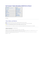
Dell Precision™ Mobile Workstation M4400 Service Manual
Model PP30L
Notes, Notices, and Cautions
If you purchased a DELL™ n Series computer, any references in this document to Microsoft
®
Windows
®
operating systems are not applicable.
Information in this document is subject to change without notice.
© 2008 Dell Inc. All rights reserved.
Reproduction in any manner whatsoever without the written permission of Dell Inc. is strictly forbidden.
Trademarks used in this text:
Dell
, the
DELL
logo, and
Dell Precision
are trademarks of Dell Inc.;
Microsoft
,
Windows, Windows Vista
, and the
Windows Start button
logo
are either
trademarks or registered trademarks of Microsoft Corporation in the United States and/or other countries.
Other trademarks and trade names may be used in this document to refer to either the entities claiming the marks and names or their products. Dell Inc. disclaims any
proprietary interest in trademarks and trade names other than its own.
August 2008
Rev. A00
Troubleshooting
LED Cover
Before Working on Your Computer
Keyboard
Base Assembly
Right Speaker Grill and
Fingerprint Reader
Hinge Covers
Flash Cache Module
Hard Drive
Palm Rest Assembly
WLAN Card
SD Card Reader
WWAN Card
Express Card Cage
WPAN/UWB Card
System Board Assembly
Fan
Modem
Heat Sinks
I/O Board
Processor Module
DC Power Cable
Memory
Display Assembly
Coin
-
Cell Battery
Flashing the BIOS
Modular Drive
NOTE:
A NOTE indicates important information that helps you make better use of your computer.
NOTICE:
A NOTICE indicates either potential damage to hardware or loss of data and tells you how to avoid the problem.
CAUTION:
A CAUTION indicates potential for property damage, personal injury, or death.