Dell M4400 Service Manual - Page 4
Replacing the Base Assembly - battery
 |
View all Dell M4400 manuals
Add to My Manuals
Save this manual to your list of manuals |
Page 4 highlights
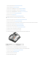
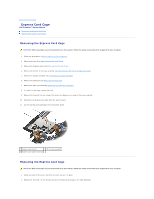
Replacing the Base Assembly The base assembly has no electronic components installed. It does include the battery latches. 1. Install the DC power cable into the base assembly. Place the external power cable connector into its mounting slot, then Route the cable through its cabling channel. 2. Install the modem cable. Place the external modem cable connector into its mounting slot, then route the cable through its cabling channel. 3. Replace the I/O board (see Replacing the I/O Board). 4. Replace the system board (see Replacing the System Board Assembly). 5. Replace the card cage (see Replacing the Express Card Cage). 6. Replace the SD card reader assembly (see Replacing the SD Card Reader). 7. Replace the PC card cage. Secure the PC card cage with two M2 x 3-mm screws. 8. Replace the palm rest assembly and thermal plate (see Replacing the Palm Rest Assembly). 9. Replace the keyboard and LED cover (see Replacing the Keyboard). 10. Replace the display assembly (see Replacing the Display Assembly). 11. Reconnect the DC power cable to the system board. 12. Replace the coin-cell battery (see Replacing the Coin-Cell Battery). 13. Replace the discrete graphics heat sink (see Replacing the Discrete Graphics Heat Sink). 14. Replace the processor heat sink (see Replacing the Processor Heat Sink). 15. Replace the fan (see Replacing the Fan). 16. Replace the memory module(s) (see Replacing a Memory Module). 17. Replace the card in the WWAN/FCM slot, if it was present (see Replacing a WWAN Card). 18. Replace the card in the WLAN/WiMax slot, if it was present (see Replacing a WLAN Card). 19. Replace the card in the WPAN/UWB/FCM slot, if it was present (see Replacing a WPAN/UWB Card). 20. Replace the modem (see Replacing the Modem). 21. Replace the bottom of the base assembly (see Replacing the Bottom of the Base Assembly). 22. Replace the modular drive (see Replacing the Modular Drive). 23. Replace the hard drive (see Replacing the Hard Drive). 24. Replace the battery (see Replacing the Battery). 25. Follow the procedure After Working on Your Computer. Back to Contents Page
-
 1
1 -
 2
2 -
 3
3 -
 4
4 -
 5
5 -
 6
6 -
 7
7 -
 8
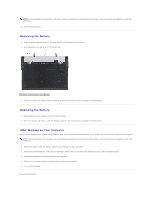
8 -
 9
9 -
 10
10 -
11
-
12
-
13
-
14
-
15
-
16
-
17
-
18
-
19
-
20
-
21
-
22
-
23
-
24
-
25
-
26
-
27
-
28
-
29
-
30
-
31
-
32
-
33
-
34
-
35
-
36
-
37
-
38
-
39
-
40
-
41
-
42
-
43
-
44
-
45
-
46
-
47
-
48
-
49
-
50
-
51
-
52
-
53
-
54
-
55
-
56
-
57
-
58
-
59
-
60
-
61
-
62
-
63
-
64
-
65
-
66
-
67
-
68
-
69
-
70
-
71
-
72
 |
 |