Dell M4400 Service Manual - Page 38
Memory - memory upgrade
 |
View all Dell M4400 manuals
Add to My Manuals
Save this manual to your list of manuals |
Page 38 highlights
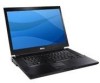
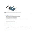
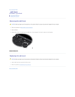
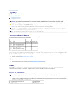
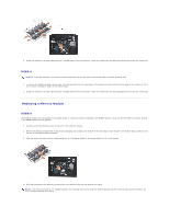
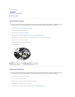
Back to Contents Page Memory Dell Precision™ Service Manual Removing a Memory Module Replacing a Memory Module Verifying System Operation CAUTION: Before you begin any of the procedures in this section, follow the safety instructions in the Dell™ Product Information Guide. CAUTION: To avoid electrostatic discharge, ground yourself by using a wrist grounding strap or by periodically touching an unpainted metal surface, such as a connector on the back of the computer. NOTICE: If your computer has only one memory module, install the memory module in the socket labeled "DIMM A". NOTICE: If you remove your original memory modules from the computer during a memory upgrade, keep them separate from any new modules that you may have, even if you purchased the new modules from Dell. If possible, do not pair an original memory module with a new memory module. Otherwise, your computer may not function at optimal performance. NOTE: Memory modules purchased from Dell are covered under your computer warranty. Removing a Memory Module Your system supports the following memory configurations: Size Slot 512 MB DIMM A 1 GB DIMM A or DIMM A and DIMM B 2 GB DIMM A or DIMM A and DIMM B 3 GB DIMM A and DIMM B 4 GB DIMM A or DIMM A and DIMM B 8 GB DIMM A and DIMM B Windows XP Windows Vista X X X X X X X X X X Your computer has two user-accessible SODIMM sockets, referred to as DIMM A and DIMM B. The socket closest to the system board, DIMM A, always contains a memory module. The DIMM B socket may contain an additional module for improved system memory performance. If the module in the DIMM A socket must be replaced and DIMM B is installed, DIMM B must be removed first. 1. Follow the procedures in Before Working on Your Computer. 2. Lay the computer upside down onto a clean, flat surface. 3. Remove the bottom of the base assembly (see Removing the Bottom of the Base Assembly). DIMM B The DIMM B socket may or may not be populated with a memory module, depending on the configuration of your system. When viewing the memory compartment from the underside of the computer, the DIMM B socket is uppermost and DIMM A is closest to the system board. Removing the DIMM B Module NOTICE: To prevent damage to the memory module connector, do not use tools to spread the memory-module retaining clips. 1. To remove the DIMM B module, spread away the retaining clips from the side edges of the memory module and lift the free edge of the module so that it sits at about a 30-degree angle to the system board. 1 memory-module retaining clips (2) 3 DIMM B module 2 memory module 4 DIMM A module
-
 1
1 -
2
-
3
-
4
-
5
-
6
-
7
-
8
-
9
-
10
-
11
-
12
-
13
-
14
-
15
-
16
-
17
-
18
-
19
-
20
-
21
-
22
-
23
-
24
-
25
-
26
-
27
-
28
-
29
-
30
-
31
-
32
-
 33
33 -
 34
34 -
 35
35 -
 36
36 -
 37
37 -
 38
38 -
 39
39 -
 40
40 -
 41
41 -
 42
42 -
 43
43 -
44
-
45
-
46
-
47
-
48
-
49
-
50
-
51
-
52
-
53
-
54
-
55
-
56
-
57
-
58
-
59
-
60
-
61
-
62
-
63
-
64
-
65
-
66
-
67
-
68
-
69
-
70
-
71
-
72
 |
 |