Denon AVR5700 Owners Manual - Page 16
Setting Up The System - avr 5700 receiver
 |
UPC - 081757503778
View all Denon AVR5700 manuals
Add to My Manuals
Save this manual to your list of manuals |
Page 16 highlights
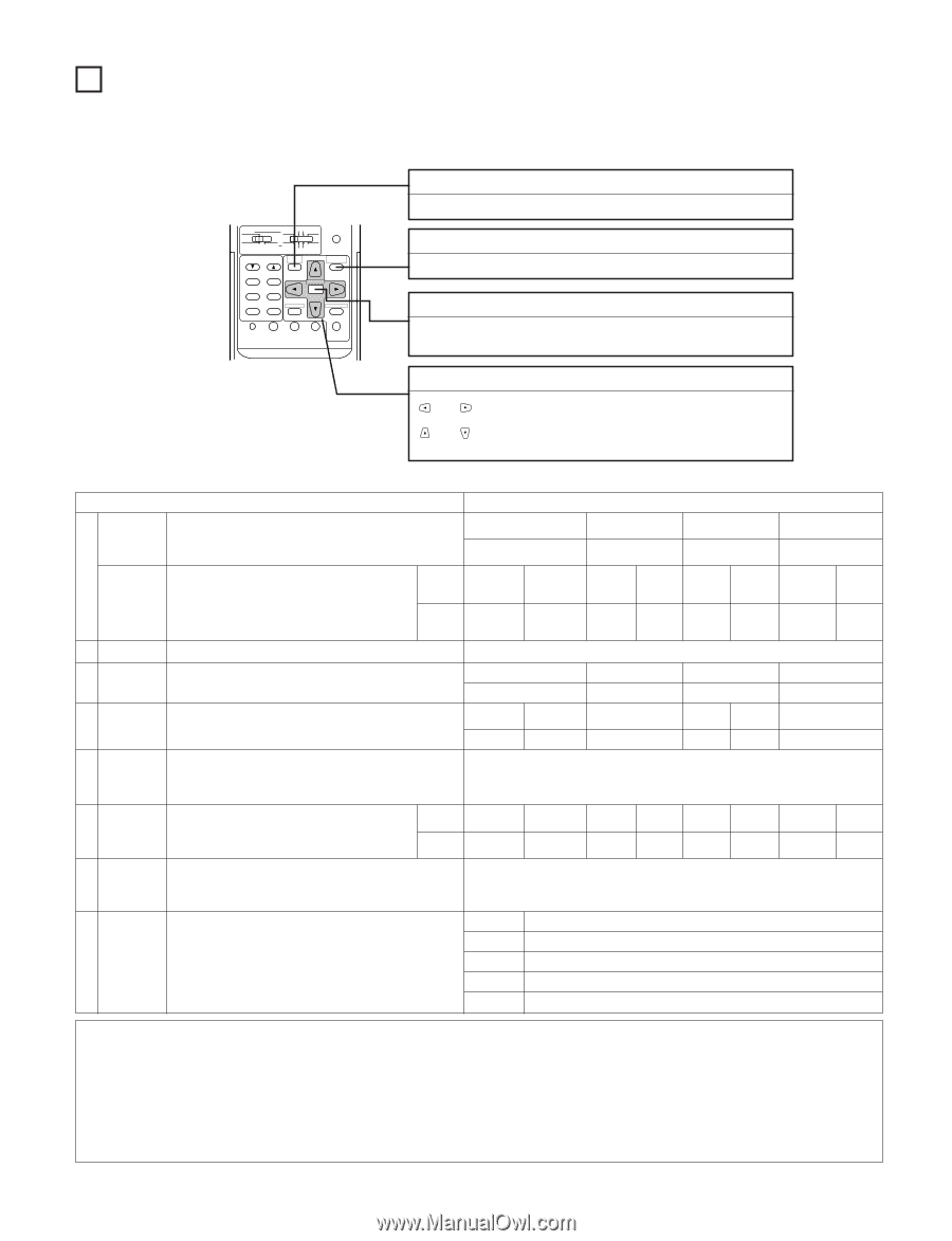
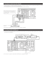
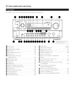
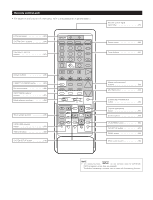
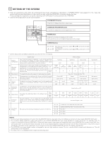
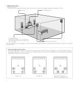
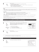
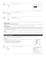
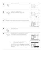
7 SETTING UP THE SYSTEM • Once all connections with other AV components have been completed as described in "CONNECTIONS" (see pages 6 to 13), make the various settings described below on the monitor screen using the AVR-5700's on-screen display function. These settings are required to set up the listening room's AV system centered around the AVR-5700. • Use the following buttons to set up the system: AUDIO DECK MD CD LOCK MUTING AVR/AVC VIDEO TUNING DVD TV VDP VCR SYSTEM SETUP SURROUND PARAMETER BAND MODE MEMORY TITLE MENU/GUIDE PANEL CH SELECT ENTER SELECT ON SCREEN DISPLAY RETURN USE/LEARN T.TONE MULTI DVD SET UP SYSTEM SETUP button Press this to display the system setup menu. SURROUND PARAMETER button Press this to display the surround parameter menu. ENTER button Press this to switch the display on the screen. Also use this button to complete the setting on the screen. CURSOR buttons and : Use these to move the cursors (0 and 1) to the left and right on the screen. and : Use these to move the cursors (• and ª) up and down on the screen. • System setup items and default values (set upon shipment from the factory) System setup Default settings Speaker Configuration Input the combination of speakers in your system and their corresponding sizes (SMALL for regular speakers, LARGE for fullsize, full-range) to automatically set the composition of the signals output from the speakers and the frequency response. Front Sp. Small Center Sp. Small Surround Sp. Small Q (Surround Speaker Setting) Use this function when using multiple surround speaker combinations for more ideal surround sound. Once the combinations of surround speakers to be used for the different surround modes are preset, the surround speakers are selected automatically according to the surround mode. Surround mode Surround speaker DOLBY/ DTS SURROUND A THX SURROUND A WIDE SCREEN A 5CH STEREO DSP SIMULA- TION A A EXT. IN A W Bass Output E Delay Time R Channel Level This selects the subwoofer speaker for playing deep bass signals. This parameter is for optimizing the timing with which the audio signals are produced from the speakers and subwoofer according to the listening position. This adjusts the volume of the signals output from the speakers and subwoofer for the different channels in order to obtain optimum effects. Front L & R 3.6 m (12 ft) Front L Front R 0 dB 0 dB Bass Out = Subwoofer Only THX Center Surround L & R 3.6 m (12 ft) Center 0 dB 3.0 m (10 ft) Surround L Surround R 0 dB 0 dB Subwoofer T Peak Limit Lev This parameter is for detecting the maximum level of the low bass signals output from the subwoofer channel in order to protect the subwoofer from damage and prevent unpleasant distorted sounds from being produced. Peak Limitter = OFF Y Digital Inputs U On Screen Display This assigns the digital input jacks for the different input sources. Input source Digital Inputs This sets whether or not to display the on-screen display that appears on the monitor screen when the controls on the remote control unit or main unit are operated (from MONITOR 1 outputs only). CD COAXIAL 1 DVD COAXIAL 2 VDP TV/DBS VCR-1 VCR-2 COAXIAL 3 OPTICAL 1 OPTICAL 2 OPTICAL 3 On Screen Display = ON A1 ~ A8 87.5/89.1/98.1/107.9/90.1/90.1/90.1/90.1 MHz I Auto Tuner Presets FM stations are received automatically and stored in the memory. B1 ~B8 C1 ~C8 D1 ~D8 520/600/1000/1400/1500/1710 kHz/90.1/90.1 MHz 90.1 MHz 90.1 MHz E1 ~E8 90.1 MHz Sub Woofer Yes - - - - Sub Woofer 3.6 m (12 ft) Subwoofer 0 dB V. AUX OPTICAL 4 TAPE-1 OPTICAL 5 NOTES: • The on-screen display signals are not output from the MONITOR OUT-2 output jack or the color difference (component) video signal (MONITOR OUT) jacks. • The on-screen display signals are output with priority to the S-VIDEO MONITOR OUT jack during playback of a video component. For example, if the TV monitor is connected to both the AVR-5700's S-Video and video monitor output jacks and signals are input to the AVR-5700 from a video source (VDP, etc.) connected to both the S-Video and video input jacks, the on-screen display signals are output with priority to the S-Video monitor output. If you wish to output the signals to the video monitor output jack, do not connect a cord to the S-VIDEO MONITOR OUT jack. (For details, see page 27.) • The AVR-5700's on-screen display function is designed for use with high resolution monitor TVs, so it may be difficult to read small characters on TVs with small screens or low resolutions. • The setup menu is not displayed when headphones are being used. 16
-
 1
1 -
2
-
3
-
4
-
5
-
6
-
7
-
8
-
9
-
10
-
 11
11 -
 12
12 -
 13
13 -
 14
14 -
 15
15 -
 16
16 -
 17
17 -
 18
18 -
 19
19 -
 20
20 -
 21
21 -
22
-
23
-
24
-
25
-
26
-
27
-
28
-
29
-
30
-
31
-
32
-
33
-
34
-
35
-
36
-
37
-
38
-
39
-
40
-
41
-
42
-
43
-
44
-
45
-
46
-
47
-
48
-
49
-
50
-
51
-
52
-
53
-
54
-
55
-
56
-
57
-
58
-
59
-
60
-
61
-
62
-
63
-
64
 |
 |