Dewalt DW744X Instruction Manual - Page 10
English - saw
 |
View all Dewalt DW744X manuals
Add to My Manuals
Save this manual to your list of manuals |
Page 10 highlights
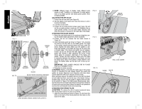
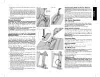
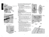
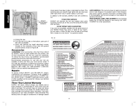
English FIG. 15 FIG. 16 FIG. 17 PADLOCK INSERTION HOLE FINE ADJUST KNOB SCREWS ON-OFF SWITCH Once made, these adjustments should remain accurate. Take a little time now to follow these directions carefully to maintain the accuracy of which your saw is capable. RAIL LOCK ADJUSTMENT 1. Lock the rail lock lever (Fig. 9) by pushing down. 2. On the underside of your saw, tighten the nut shown in Figure 18. Adjust this nut until the gap between the belleville washers closes. 3. Once the springs are almost touching, tighten the nut 1/2 turn. RIP SCALE ADJUSTMENT See Adjusting the Rip Scale. BLADE ALIGNMENT ADJUSTMENT (Blade Parallel to Miter Slot) WARNING: Cut Hazard. Check the blade at 0˚ and 45˚ to make sure blade does not hit the throat plate, causing personal injury. If the blade appears to be out of alignment with the miter slot on the table top, it will require calibration for alignment. To realign the blade and miter slot, use the following procedure: 1. THE SAW MUST BE UNPLUGGED BEFORE YOU MAKE ANY ADJUSTMENT TO THE BLADE. 2. Place the unit in an upright position. Using a 10mm socket, loosen rear pivot bracket fasteners just enough to allow the bracket to move side-to-side (Fig. 7A). 3. Adjust the bracket until the blade is parallel to the miter gauge slot. 4. Tighten the rear pivot bracket fasteners to 6-8 ft.lbs. (8.1 to 10.8 Nm). BEVEL STOP AND POINTER ADJUSTMENT 1. Raise the blade fully by rotating the blade height adjustment wheel clockwise until it stops. 2. Unlock the bevel lock lever (Fig. 3) by pushing it up and to the right. Loosen the bevel stop screw (Fig. 19). 3. Place a square flat against the table top and against the blade between teeth, as shown in Figure 20. Ensure the bevel lock lever is in its unlocked, or up, position. 4. Using the bevel lock lever, adjust the bevel angle until it is flat against the square. 5. Tighten the bevel lock lever by pushing it down. 6. Turn the bevel stop cam until it firmly contacts the bearing block. Tighten the bevel stop screw. 7. Check the bevel angle scale. If the pointer does not read 0°, loosen pointer screw (Fig. 19) and move the pointer so it reads correctly. Retighten the pointer screw. 8. Repeat at 45°, but do not adjust pointer. FIG. 18 FIG. 19 WARNING FIG. 20 NUT BEVEL STOP SCREW BELVILLE WASHERS GAP BEVEL STOP CAM POINTER SCREW 8
-
 1
1 -
2
-
3
-
4
-
 5
5 -
 6
6 -
 7
7 -
 8
8 -
 9
9 -
 10
10 -
 11
11 -
 12
12 -
 13
13 -
 14
14 -
 15
15 -
16
-
17
-
18
-
19
-
20
-
21
-
22
-
23
-
24
-
25
-
26
-
27
-
28
-
29
-
30
-
31
-
32
-
33
-
34
-
35
-
36
-
37
-
38
-
39
-
40
-
41
-
42
-
43
-
44
 |
 |
