Dewalt DW744X Instruction Manual - Page 8
Warning, Caution - 10 table saw
 |
View all Dewalt DW744X manuals
Add to My Manuals
Save this manual to your list of manuals |
Page 8 highlights
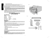
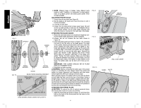
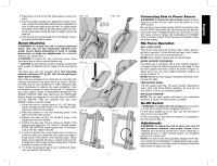
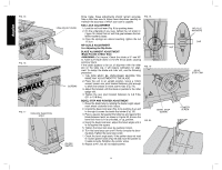
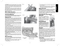
English FIG. 6 FIG. 7 SPINDLE ARBOR NUT INNER WASHER OUTER WASHER BLADE FIG. 7A REAR PINION BEARING ASSEMBLY REAR PIVOT BRACKET TORX HEAD BOLTS 10MM HEX BOLTS (SAW SHOWN UPSIDE DOWN FOR CLARITY) 6. NOTE: Different types of blades make different kerfs (width of cuts). Therefore, it is necessary to check adjustment of rip fence pointer and blade guard splitter when changing blades. ADJUSTING THE RIP SCALE 1. Unlock the rail lock lever (see Figure 9). 2. Set the blade at 0Þ bevel and move the fence in until it touches the blade. 3. Lock the rail lock lever. 4. Loosen the rip scale pointer screws (see Figure 16) and set the rip scale pointer to read zero (0). Retighten the rip scale pointer screws. The rip scale reads correctly only when the fence is mounted on the right side of the blade. ATTACHING THE BLADE GUARD 1. Raise the saw blade arbor to its maximum height by turning the blade height adjustment wheel clockwise. 2. Loosen, but do not remove the two bolts shown in Figure 10. 3. Insert the blade guard as shown in Figure 11A, ensuring the bolts fit into the slots on the blade guard. The edge of the splitter should protrude below and hook under the shims. Tighten the bolts. Make sure the splitter is centered and parallel to the blade by lining up the parts with a straight edge. If the blade and splitter are not aligned, loosen, but do not remove the bolts again. Remove the guard and reinsert it after adjusting the shims. These shims allow for precision alignment of the blade and splitter. Tighten the bolts securely. Make sure that there is clearance between the splitter and the blade, and that the blade spins freely. If the splitter is tilted relative to the blade, the splitter plate can be bent until it lines up correctly. IMPORTANT: THE GUARD SHOULD BE IN PLACE FOR ALL POSSIBLE CUTS. 4. Retighten the bolts securely. WARNING: Before connecting the table saw to the power source or operating the saw, always inspect the guard and splitter for proper alignment and clearance with saw blade. Check alignment after each change of bevel angle. When properly aligned, the splitter will be in line with the blade at both table top level, and at the top of the blade. Using a straight edge, ensure that the blade is aligned with the splitter as shown in Figure 11B. With power disconnected, operate the blade tilt and height adjustments through the extremes of travel and insure the guard clears the blade in all operations and that the anti-kickback teeth are functioning. ATTACHING THE THROAT PLATE CAUTION: To reduce the risk of serious personal injury, the throat plate must be in place at all times. 1. Align the throat plate as shown in Figure 12, and insert the tabs on the back of the throat plate into the holes on the back of the table. 6 FIG. 8 FIG. 9 FIG. 10 ARBOR WRENCH RAIL LOCK LEVER SHIMS BOLTS
-
 1
1 -
2
-
 3
3 -
 4
4 -
 5
5 -
 6
6 -
 7
7 -
 8
8 -
 9
9 -
 10
10 -
 11
11 -
 12
12 -
 13
13 -
14
-
15
-
16
-
17
-
18
-
19
-
20
-
21
-
22
-
23
-
24
-
25
-
26
-
27
-
28
-
29
-
30
-
31
-
32
-
33
-
34
-
35
-
36
-
37
-
38
-
39
-
40
-
41
-
42
-
43
-
44
 |
 |
