Epson Stylus Pro 9000 Service Manual - Page 163
Handshaking, Adaptable connector, Recommended I/F cable, Table 7-6., Serial Interface Pin Assignment
 |
View all Epson Stylus Pro 9000 manuals
Add to My Manuals
Save this manual to your list of manuals |
Page 163 highlights
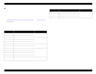
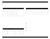
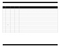
EPSON Stylus Pro 9000 Handshaking X-ON/X-OFF, DTR protocol Adaptable connector 8-pin mini-DIN Recommended I/F cable Apple system peripheral-8 cable (M0197) Table 7-6. Serial Interface Pin Assignment Pin No. Signal Name Direction Description 1 SCLK Out Synchronous clock signal 2 CTS In Clear To Send 3 TXD- Out Transmit Data (-) 4 SG In Signal Ground 5 RXD- In Receive Data (-) 6 TXD+ Out Balanced Transmit Data (+) 7 DTR Out Data Terminal Ready 8 RXD+ In Balanced Receive Data (+) State Busy Ready Table 7-7. X-On/X-Off and DTR Protocol Buffer Space X-ON/X-OFF Less than 3072 bytes Send X-OFF code More than 5120 bytes Send X-ON code DTR OFF ON Appendix 163
-
 1
1 -
2
-
3
-
4
-
5
-
6
-
7
-
8
-
9
-
10
-
11
-
12
-
13
-
14
-
15
-
16
-
17
-
18
-
19
-
20
-
21
-
22
-
23
-
24
-
25
-
26
-
27
-
28
-
29
-
30
-
31
-
32
-
33
-
34
-
35
-
36
-
37
-
38
-
39
-
40
-
41
-
42
-
43
-
44
-
45
-
46
-
47
-
48
-
49
-
50
-
51
-
52
-
53
-
54
-
55
-
56
-
57
-
58
-
59
-
60
-
61
-
62
-
63
-
64
-
65
-
66
-
67
-
68
-
69
-
70
-
71
-
72
-
73
-
74
-
75
-
76
-
77
-
78
-
79
-
80
-
81
-
82
-
83
-
84
-
85
-
86
-
87
-
88
-
89
-
90
-
91
-
92
-
93
-
94
-
95
-
96
-
97
-
98
-
99
-
100
-
101
-
102
-
103
-
104
-
105
-
106
-
107
-
108
-
109
-
110
-
111
-
112
-
113
-
114
-
115
-
116
-
117
-
118
-
119
-
120
-
121
-
122
-
123
-
124
-
125
-
126
-
127
-
128
-
129
-
130
-
131
-
132
-
133
-
134
-
135
-
136
-
137
-
138
-
139
-
140
-
141
-
142
-
143
-
144
-
145
-
146
-
147
-
148
-
149
-
150
-
151
-
152
-
153
-
154
-
155
-
156
-
157
-
 158
158 -
 159
159 -
 160
160 -
 161
161 -
 162
162 -
 163
163 -
 164
164 -
 165
165 -
 166
166 -
 167
167 -
 168
168 -
169
-
170
-
171
-
172
-
173
-
174
-
175
-
176
-
177
-
178
-
179
-
180
-
181
-
182
-
183
-
184
-
185
-
186
-
187
-
188
-
189
-
190
-
191
-
192
-
193
-
194
-
195
-
196
-
197
-
198
 |
 |

EPSON Stylus Pro 9000
Appendix
163
Handshaking
X-ON/X-OFF, DTR protocol
Adaptable connector
8-pin mini-DIN
Recommended I/F cable
Apple system peripheral-8 cable (M0197)
Table 7-6.
Serial Interface Pin Assignment
Table 7-7.
X-On/X-Off and DTR Protocol
Pin No.
Signal Name
Direction
Description
1
SCLK
Out
Synchronous clock signal
2
CTS
In
Clear To Send
3
TXD-
Out
Transmit Data (-)
4
SG
In
Signal Ground
5
RXD-
In
Receive Data (-)
6
TXD+
Out
Balanced Transmit Data (+)
7
DTR
Out
Data Terminal Ready
8
RXD+
In
Balanced Receive Data (+)
State
Buffer Space
X-ON/X-OFF
DTR
Busy
Less than 3072 bytes
Send X-OFF code
OFF
Ready
More than 5120 bytes
Send X-ON code
ON