Epson Stylus Pro 9000 Service Manual - Page 99
Confirming the tube guide assembly position, At this point in re-assembly
 |
View all Epson Stylus Pro 9000 manuals
Add to My Manuals
Save this manual to your list of manuals |
Page 99 highlights
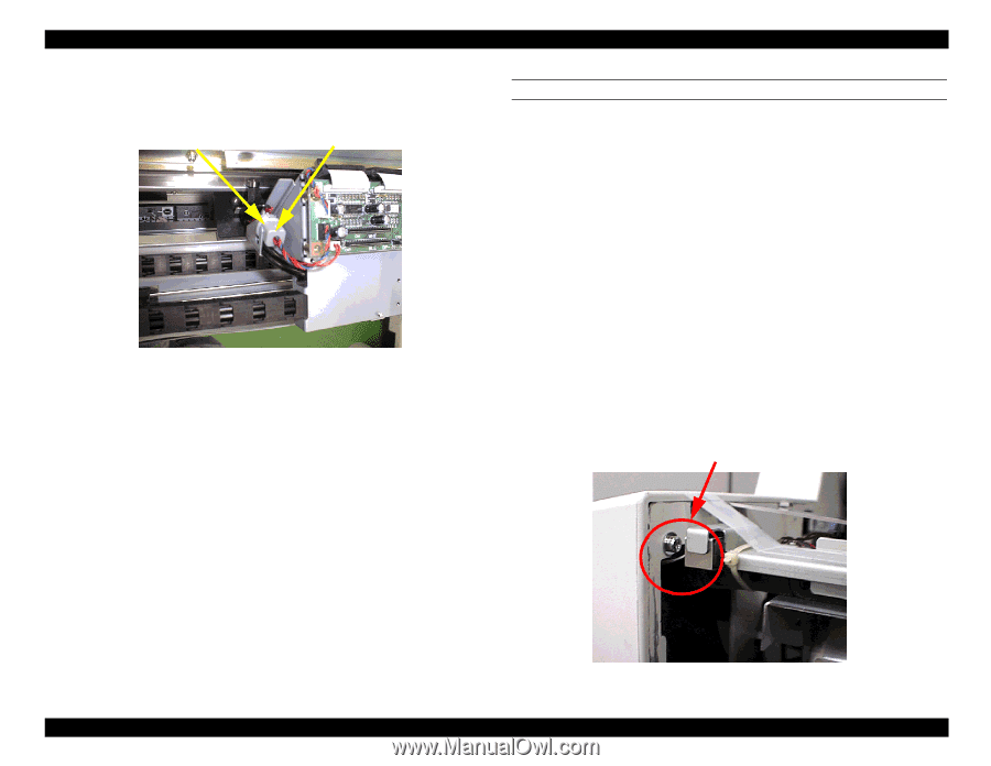
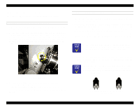
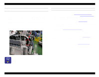
EPSON Stylus Pro 9000 13. Secure the dark-colored ink tubes and ferrite core to the cable connection plate with the plastic insulation lock (KI-100M). Insulation lock (KI-100M) Ferrite core NOTE: At this point in re-assembly, the tube guide assembly (tube guide, FFCs, and protective film) is attached to the cable connection plate with the cable support. CONFIRMING THE TUBE GUIDE ASSEMBLY POSITION 1. Move the carriage all the way from one side to the other to make sure the tube guide assemblies stay centered in the carriage path. If any part of the tube guide assembly on the left moves laterally (towards the front or back of the printer), loosen the ink pipe fixing side of the tube guide fixing plate and CR cable pressing plate. Then adjust the tube guide assembly so that it is centered, and secure the tube guide fixing plate and CR cable fixing plate. If any part of the tube guide assembly on the right moves laterally, loosen the tube guide cover and CR cable fixing plate. Then adjust the tube guide assembly so that it is centered, and secure the tube guide cover and CR cable fixing plate. 2. Squeeze the FFC ferrite core and the cable support together, and secure them with the plastic insulation lock (T18L). 3. Move the carriage to the left so that the left edge of the CR board is 43 mm from the left-side frame. Make sure the ferrite core and cable support do not touch the frame or screw. Also, make sure the FFC and protective film do not touch or rub against the frame. If there is a problem, loosen the tube guide fixing plates in the center and adjust the position of the edge of the tube guide. Make sure nothing touches the left-side frame. Disassembly & Assembly 4. Attach the new CR board cover. 99
-
 1
1 -
2
-
3
-
4
-
5
-
6
-
7
-
8
-
9
-
10
-
11
-
12
-
13
-
14
-
15
-
16
-
17
-
18
-
19
-
20
-
21
-
22
-
23
-
24
-
25
-
26
-
27
-
28
-
29
-
30
-
31
-
32
-
33
-
34
-
35
-
36
-
37
-
38
-
39
-
40
-
41
-
42
-
43
-
44
-
45
-
46
-
47
-
48
-
49
-
50
-
51
-
52
-
53
-
54
-
55
-
56
-
57
-
58
-
59
-
60
-
61
-
62
-
63
-
64
-
65
-
66
-
67
-
68
-
69
-
70
-
71
-
72
-
73
-
74
-
75
-
76
-
77
-
78
-
79
-
80
-
81
-
82
-
83
-
84
-
85
-
86
-
87
-
88
-
89
-
90
-
91
-
92
-
93
-
 94
94 -
 95
95 -
 96
96 -
 97
97 -
 98
98 -
 99
99 -
 100
100 -
 101
101 -
 102
102 -
 103
103 -
 104
104 -
105
-
106
-
107
-
108
-
109
-
110
-
111
-
112
-
113
-
114
-
115
-
116
-
117
-
118
-
119
-
120
-
121
-
122
-
123
-
124
-
125
-
126
-
127
-
128
-
129
-
130
-
131
-
132
-
133
-
134
-
135
-
136
-
137
-
138
-
139
-
140
-
141
-
142
-
143
-
144
-
145
-
146
-
147
-
148
-
149
-
150
-
151
-
152
-
153
-
154
-
155
-
156
-
157
-
158
-
159
-
160
-
161
-
162
-
163
-
164
-
165
-
166
-
167
-
168
-
169
-
170
-
171
-
172
-
173
-
174
-
175
-
176
-
177
-
178
-
179
-
180
-
181
-
182
-
183
-
184
-
185
-
186
-
187
-
188
-
189
-
190
-
191
-
192
-
193
-
194
-
195
-
196
-
197
-
198
 |
 |