Fluke 724 Fluke 724 Users Manual
Fluke 724 Manual
 |
View all Fluke 724 manuals
Add to My Manuals
Save this manual to your list of manuals |
Fluke 724 manual content summary:
- Fluke 724 | Fluke 724 Users Manual - Page 1
February 2000 Rev.1, 8/03 © 2000-2003 Fluke Corporation. All rights reserved. All product names are trademarks of their respective companies. ® 724 Temperature Calibrator Users Manual - Fluke 724 | Fluke 724 Users Manual - Page 2
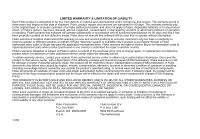
period is three years and begins on the date of shipment. Parts, product repairs and services are warranted for 90 days. This warranty extends only to the original buyer or end-user customer of a Fluke authorized reseller, and does not apply to fuses, disposable batteries or to any product which, in - Fluke 724 | Fluke 724 Users Manual - Page 3
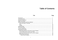
of Contents Title Page Introduction...1 Contacting Fluke...1 Standard Equipment ...3 Safety Information...3 Getting Acquainted with the Calibrator 8 Input and Output Terminals 8 Keys 17 Measuring Electrical Parameters (Lower Display 19 Measuring Temperature 20 Using Thermocouples 20 i - Fluke 724 | Fluke 724 Users Manual - Page 4
the Calibrator 36 Service Center Calibration or Repair 36 Replacement Parts ...37 Specifications ...39 DC Voltage Measurement 39 DC Voltage Source...39 DC mA Measurement 39 Ohms Measurement 40 Ohms Source...40 Millivolt Measurement and Source 41 Temperature, Thermocouples 41 Temperature, RTD - Fluke 724 | Fluke 724 Users Manual - Page 5
Temperature Calibrator Contents (continued) General Specifications 43 Index ...45 iii - Fluke 724 | Fluke 724 Users Manual - Page 6
724 Users Manual iv - Fluke 724 | Fluke 724 Users Manual - Page 7
List of Tables Table Title Page 1. Summary of Source and Measure Functions 2 2. International Symbols ...7 3. Input/Output Terminals and Connectors 9 4. Key Functions ...11 5. Thermocouple Types Accepted 21 6. RTD Types Accepted...24 7. Replacement Parts ...37 v - Fluke 724 | Fluke 724 Users Manual - Page 8
724 Users Manual vi - Fluke 724 | Fluke 724 Users Manual - Page 9
Thermocouple 22 11. Measuring Temperature with an RTD, Measuring 2-, 3-, and 4-Wire Resistance 25 12. Electrical Sourcing Connections 26 13. Connections for Simulating a Thermocouple 28 14. Connection for Simulating a 3-Wire RTD 29 15. Calibrating a Thermocouple Transmitter 33 16. Calibrating - Fluke 724 | Fluke 724 Users Manual - Page 10
724 Users Manual viii - Fluke 724 | Fluke 724 Users Manual - Page 11
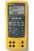
Temperature Calibrator Introduction Your Fluke 724 Temperature Calibrator is a handheld, battery-operated instrument that measures and sources a variety of thermocouples and RTDs. See Table 1. In addition to the functions in Table 1, the calibrator has the following features and functions: • A - Fluke 724 | Fluke 724 Users Manual - Page 12
724 Users Manual Function dc V Resistance Thermocouple RTD (ResistanceTemperature Detector) Other functions Table 1. Summary of Source and Measure Functions Measure Source 0 V to30 V 0 V to10 V 0 Ω to 3200 Ω 15 Ω to 3200 Ω Types E, J, K, T, B, R, S, L, U, N, mV Pt100 Ω (385) Pt100 Ω ( - Fluke 724 | Fluke 724 Users Manual - Page 13
order replacement parts or spares, see the user-replaceable parts list in Table 7. • TL75 test leads (one set) • Alligator clips (one set) • Stackable alligator clip test leads (one set) • 724 Product Overview Manual • 724 CD-ROM (contains Users Manual) • Spare fuse Temperature Calibrator Standard - Fluke 724 | Fluke 724 Users Manual - Page 14
guards on the probes. • Connect the common test lead before you connect the live test lead. When you disconnect test leads, disconnect the live test lead first. • Do not use the calibrator if it operates abnormally. Protection may be impaired. When in doubt, have the calibrator serviced. • Do not - Fluke 724 | Fluke 724 Users Manual - Page 15
Temperature Calibrator Safety Information W Warning • Use only 4 AA batteries, properly installed in the calibrator case, to power the calibrator. • Disconnect test leads before changing to another measure or source function. • When servicing the calibrator, use only specified replacement parts. • - Fluke 724 | Fluke 724 Users Manual - Page 16
724 Users Manual Alligator Clips TL75 Test Lead Set Stackable Test Leads SSETTOURPE RECALL 100% 25% 25% 0% SOURCE / 30V MAX MEASURE ALL TERMINALS 3W MEASURE V TC V mA RTD mA- LOOP 4W COM COM Figure 1. Standard Equipment zi01f.eps 6 - Fluke 724 | Fluke 724 Users Manual - Page 17
Temperature Calibrator Safety Information Table 2. International Symbols AC - Alternating current Double insulated DC - Direct current Earth ground Pressure Conforms to Canadian Standards Association directives Battery Refer to the manual for information about this feature. O ON/OFF - Fluke 724 | Fluke 724 Users Manual - Page 18
724 Users Manual Getting Acquainted with the Calibrator Input and Output Terminals Figure 2 shows the calibrator input and output terminals. Table 3 explains their use. 724 TEMPERATURE CALIBRATOR V mA LOOP MEAS V SOURCE TC STORE SETUP RECALL ˚C RTD ˚F 100% 25% 25% 0% 1 7 2 6 54 3 - Fluke 724 | Fluke 724 Users Manual - Page 19
loop power. Terminal for measuring or simulating thermocouples. This terminal accepts a miniature polarized thermocouple plug with flat, in-line blades spaced 7.9 mm (0.312 in) center to center. Terminals for sourcing or measuring voltage, resistance, and RTDs. Terminals for performing 3W and 4W - Fluke 724 | Fluke 724 Users Manual - Page 20
724 Users Manual Keys Figure 3 shows the calibrator keys and Table 4 explains their use. 724 TEMPERATURE CALIBRATOR 2 V mA LOOP MEAS V ˚C 1 SOURCE TC RTD ˚F STORE SETUP RECALL 100% 25% 25% 0% 30V MAX ALL TERMINALS SOURCE / MEASURE mA+ 3W V TC RTD MEASURE V mA LOOP mA- 4W COM - Fluke 724 | Fluke 724 Users Manual - Page 21
Temperature Calibrator Getting Acquainted with the Calibrator No Name AO BV CA DK EC FF adjust mode on when powering up. Displays temperature in degrees Celsius when in TC or RTD functions. Displays temperature in degrees Fahrenheit when in TC or RTD functions. Recalls from memory a source value - Fluke 724 | Fluke 724 Users Manual - Page 22
724 Users Manual No L AM AM M N O P Q R S T Name L OY OZ XW Y Z Q S M T V R U Table 4. Key wire selections. Moves through the eight memory locations of calibrator thermocouple types. Toggles between voltage, sourcing, and measuring functions in the lower display. Selects RTD (resistance temperature - Fluke 724 | Fluke 724 Users Manual - Page 23
Display Figure 4 shows the elements of a typical display. Temperature Calibrator Getting Acquainted with the Calibrator Low Battery Symbol Mode Indicator Loop Annunciator Memory Locations for Calibrator Setups Units Display Auto Ramp Figure 4. Elements of a Typical Display sh07f.eps 13 - Fluke 724 | Fluke 724 Users Manual - Page 24
724 Users Manual Getting Started This section acquaints you with some basic operations of the calibrator. Proceed as follows to perform a voltage-to-voltage test: 1. Connect the calibrator's voltage output to its voltage input as shown in Figure 5. 2. Press O to turn on the calibrator. Press l to - Fluke 724 | Fluke 724 Users Manual - Page 25
Temperature Calibrator Shut Down Mode 724 TEMPERATURE CALIBRATOR V mA LOOP MEAS V SOURCE TC SSETTOURPE RECALL ˚C RTD ˚F 100% 25% 25% 0% Figure 5. Voltage-to-Voltage Test zi04f.eps 15 - Fluke 724 | Fluke 724 Users Manual - Page 26
724 Users Manual Contrast Adjustment Note Available with V2.1 Firmware or greater. To hold W to lighten contrast. 4. Press S to save the contrast level. 16 724 TEMPERATURE CALIBRATOR 1 V mA LOOP 2 MEAS V ˚C SOURCE TC RTD ˚F STORE SETUP RECALL 100% 25% 25% 4 0% 3 Figure 6. Adjusting - Fluke 724 | Fluke 724 Users Manual - Page 27
as follows: 1. Connect the calibrator to the transmitter current loop terminals as shown in Figure 8. 2. Press K while the calibrator is in current measurement mode. LOOP appears and an internal 24 V loop supply turns on. Temperature Calibrator Using Measure Mode 724 TEMPERATURE CALIBRATOR V mA - Fluke 724 | Fluke 724 Users Manual - Page 28
724 Users Manual 724 TEMPERATURE CALIBRATOR V mA LOOP MEAS V SOURCE TC STORE SETUP RECALL ˚C RTD ˚F 100% 25% 25% 0% Red TEST DC PWR - ++ - +- Black Figure 8. Connections for Supplying Loop Power 18 zi06f.eps - Fluke 724 | Fluke 724 Users Manual - Page 29
: 1. Connect the calibrator as shown in Figure 9. M 2. If necessary, press for MEASURE mode (lower display) 3. Press l for dc voltage or current, or U for resistance. Temperature Calibrator Using Measure Mode 724 TEMPERATURE CALIBRATOR V mA LOOP MEAS V SOURCE TC STORE SETUP RECALL ˚C RTD - Fluke 724 | Fluke 724 Users Manual - Page 30
724 Users Manual Measuring Temperature Using Thermocouples The calibrator supports ten standard thermocouples, including types E, N, J, K, T, B, R, S, L, or U. Table 5 summarizes the ranges and characteristics of the supported thermocouples. To measure temperature using a thermocouple, proceed as - Fluke 724 | Fluke 724 Users Manual - Page 31
Temperature Calibrator Using Measure Mode Table 5. Thermocouple Types Accepted Type Positive Lead Material Positive Lead (H) Color ANSI* IEC** Negative Lead Material E Chromel Purple Violet Constantan N Ni-Cr-Si Orange Pink Ni-Si- - Fluke 724 | Fluke 724 Users Manual - Page 32
724 Users Manual 30V MAX ALL TERMINALS SOURCE / MEASURE MEASURE 3W V TC V mA RTD LOOP TC 4W COM COM TC Miniplug Process Temperature Warning 30 V maximum to Figure 10. Measuring Temperature with a Thermocouple zi14f.eps 22 - Fluke 724 | Fluke 724 Users Manual - Page 33
-, or four-wire connections, with the three-wire connection the most common. A four-wire configuration provides the highest measurement precision, and two-wire provides the lowest measurement precision. Temperature Calibrator Using Measure Mode To measure temperature using an RTD input, proceed - Fluke 724 | Fluke 724 Users Manual - Page 34
724 Users Manual Table 6. RTD Types Accepted RTD Type Ice Point (R ) 0 Material α Range (°C) Pt100 (3926) 100 Ω Platinum 0.003926 Ω/°C -200 to 630 Pt100 ( is Pt100 (3916), α = 0.003916 Ω/°C. (Also designated as JIS curve.) The IEC standard RTD is the Pt100 (385), α = 0.00385 Ω/°C. 24 - Fluke 724 | Fluke 724 Users Manual - Page 35
Calibrator Using Measure Mode RTD Resistance to be measured RTD Resistance to be measured 4W 30V MAX ALL TERMINALS SOURCE / MEASURE MEASURE 3W V TC V mA RTD LOOP 4W COM COM RTD Resistance to be measured Figure 11. Measuring Temperature with an RTD, Measuring 2-, 3-, and 4-Wire - Fluke 724 | Fluke 724 Users Manual - Page 36
724 Users Manual Using Source Mode In SOURCE mode, the calibrator generates calibrated signals for testing and calibrating process instruments, supplies voltages and resistances, and simulates the electrical output of RTD and thermocouple temperature sensors. Sourcing Electrical Parameters Volts or - Fluke 724 | Fluke 724 Users Manual - Page 37
calibrator simulates a 2-wire RTD at its front panel. To connect to a 3-wire or 4-wire transmitter, use the stacking cables to provide the extra wires. See Figure 14. 3. Enter the temperature you want by pressing X and W keys. Press Y and Z to select a different digit to edit. 4. If the 724 display - Fluke 724 | Fluke 724 Users Manual - Page 38
724 Users Manual 724 TEMPERATURE CALIBRATOR V mA LOOP MEAS V SOURCE TC STORE SETUP RECALL ˚C RTD ˚F 100% 25% 25% 0% TC Color depends on type of TC TEST DC PWR - ++ +- TC Miniplug Figure 13. Connections for Simulating a Thermocouple 28 zi10f.eps - Fluke 724 | Fluke 724 Users Manual - Page 39
724 TEMPERATURE CALIBRATOR V mA LOOP MEAS V SOURCE TC SSETTOURPE RECALL ˚C RTD ˚F 100% 25% 25% 0% BLACK BLACK Temperature Calibrator Using Source Mode SENSOR TERMINALS 1 4 3 2 RED Figure 14. Connections for Simulating 3-Wire RTD zi11f.eps 29 - Fluke 724 | Fluke 724 Users Manual - Page 40
724 Users Manual Setting 0 % and 100 % Output Parameters For output parameters (volts, ohms, TC potentials or RTD resistances), you must set the 0 % and 100 % points before you can use the step and ramp functions. Proceed as follows: M 1. If necessary, press for SOURCE - Fluke 724 | Fluke 724 Users Manual - Page 41
-second smooth ramp • N 0 % - 100 % - 0 % Stair-step ramp in 25 % steps, pausing 5 seconds at each step. To exit ramping, press any button. Temperature Calibrator Storing and Recalling Setups Storing and Recalling Setups You can store up to eight of your settings in a nonvolatile memory and recall - Fluke 724 | Fluke 724 Users Manual - Page 42
724 Users Manual Calibrating a Transmitter Use the measurement (upper display) and source (lower display) modes to calibrate a transmitter. The following example shows how to calibrate a temperature transmitter. Connect the calibrator to the instrument under test as shown in Figure 15. Proceed as - Fluke 724 | Fluke 724 Users Manual - Page 43
724 TEMPERATURE CALIBRATOR V mA LOOP MEAS V SOURCE TC STORE SETUP RECALL ˚C RTD ˚F 100% 25% 25% 0% Temperature Calibrator Calibrating a Transmitter Red TEST DC PWR - ++ - +- Black Figure 15. Calibrating a Thermocouple Transmitter zi12f.eps 33 - Fluke 724 | Fluke 724 Users Manual - Page 44
724 Users Manual Testing an Output Device Use the source functions to test and calibrate actuators, recording, and indicating devices. Proceed as follows: 1. Connect mode. 34 724 TEMPERATURE CALIBRATOR Red 0 to 1 V dc Input V mA LOOP MEAS V SOURCE TC STORE SETUP RECALL ˚C RTD ˚F 100% 25 - Fluke 724 | Fluke 724 Users Manual - Page 45
resistance. A value of < 10 Ω is good. Problems while measuring using the right jacks indicate that F3 may have opened. To replace the fuse, refer to Figure 17 and perform the following steps: Temperature Calibrator Replacing the Batteries 1. Turn the calibrator off, remove the test leads from the - Fluke 724 | Fluke 724 Users Manual - Page 46
724 Users Manual Battery and Compartment Fuse Compartment Figure 17. Replacing the Batteries sh38f.eps 36 Maintenance Cleaning the Calibrator W Warning To avoid personal injury or damage to the calibrator, use only the specified replacement parts and do not allow water into the case. Caution - Fluke 724 | Fluke 724 Users Manual - Page 47
to the nearest Service Center. Fluke assumes no responsibility for damage in transit. The Fluke 724 Temperature Calibrator covered by the warranty will be promptly repaired or replaced (at Fluke's option) and returned to you at no charge. See the warranty at the beginning of this manual for warranty - Fluke 724 | Fluke 724 Users Manual - Page 48
724 Users Manual 17 1 22 9 20 6 19 38 8 7 3 2 3 4 5 16 18 6 21 23 Figure 18. Replacement Parts 10 11 12 13 14 15 zi46f.eps - Fluke 724 | Fluke 724 Users Manual - Page 49
-10 °C to 18 °C, +28 °C to 55 °C: ±0.005 % of range per °C Temperature Calibrator Specifications DC Voltage Source Range Resolution Accuracy, (% of Reading + Counts) 100 mV 0.01 mV 0.02 % + 2 10 V 0.001 V 0.02 % + 2 Temperature coefficient -10 °C to 18 °C, +28 °C to 55 °C: ±0.005 % of range - Fluke 724 | Fluke 724 Users Manual - Page 50
724 Users Manual Ohms Measurement Accuracy ± Ω Ohms Range 4-Wire 2- and 3-Wire* 0 to 400 Ω 0.1 0.15 400 to 1.5 kΩ 0.5 1.0 1.5 to 3.2 kΩ 1 1.5 Excitation Current: 0.2 mA Maximum input voltage: 30 V Temperature coefficient -10 °C to 18 °C, +28 °C to 55 °C: ± 0.005 % of range per °C * 2- - Fluke 724 | Fluke 724 Users Manual - Page 51
. Temperature, Thermocouples Type Range Measure and Source Accuracies (ITS-90) J -200 to 0 °C 0 to 1200 °C K -200 to 0 °C 0 to 1370 °C T -200 to 0 °C 0 to 400 °C E -200 to 0 °C 0 to 950 °C 1.0 °C 0.7 °C 1.2 °C 0.8 °C 1.2 °C 0.8 °C 0.9 °C 0.7 °C Temperature Calibrator Specifications - Fluke 724 | Fluke 724 Users Manual - Page 52
724 Users Manual Temperature, RTD Ranges, and Accuracies (ITS-90) Accuracy Type Range °C Measure 4-Wire °C Measure 2- and 3-Wire* °C Source °C Ni120 -80 to 260 0.2 0.3 0.2 Pt100-385 - 200 to 800 0.33 0.5 0.33 Pt100-392 -200 to 630 0.3 0.5 0.3 Pt100-JIS -200 to 630 0.3 0.5 - Fluke 724 | Fluke 724 Users Manual - Page 53
Temperature Calibrator Specifications Loop Power Supply Voltage: 24 V Maximum current: 22 mA Short circuit protected General Specifications Operating temperature Storage temperature Operating altitude Relative Humidity (% RH operating without condensation) Vibration Safety Power requirements Size - Fluke 724 | Fluke 724 Users Manual - Page 54
724 Users Manual 44 - Fluke 724 | Fluke 724 Users Manual - Page 55
Auto ramping output, 31 -B- Batteries, replacing, 35 -C- Calibration, 36 Cleaning calibrator, 36 -D- Display, 13 -E- Electrical parameters measurement, 19 sourcing -M- Measure functions, summary (table), 2 Measure mode, 17 Measuring temperature with RTDs, 23 temperature with thermocouples, 20 45 - Fluke 724 | Fluke 724 Users Manual - Page 56
724 Users Manual -O- Output device, testing, 34 Output terminals, 8 -P- Parts list, 37 -R- Recalling setups, 31 Repair, 36 RTD simulating, 27 RTD measuring, 23 types, 23 -S- Safety information, 3 Servicing, 36 Setup recalling, 31 storing, 31 Thermocouple, 27 Simulating RTD, 27 thermocouples, 27
-
 1
1 -
 2
2 -
 3
3 -
 4
4 -
 5
5 -
 6
6 -
 7
7 -
8
-
9
-
10
-
11
-
12
-
13
-
14
-
15
-
16
-
17
-
18
-
19
-
20
-
21
-
22
-
23
-
24
-
25
-
26
-
27
-
28
-
29
-
30
-
31
-
32
-
33
-
34
-
35
-
36
-
37
-
38
-
39
-
40
-
41
-
42
-
43
-
44
-
45
-
46
-
47
-
48
-
49
-
50
-
51
-
52
-
53
-
54
-
55
-
56
 |
 |

®
724
Temperature Calibrator
Users Manual
February 2000 Rev.1, 8/03
© 2000-2003 Fluke Corporation. All rights reserved.
All product names are trademarks of their respective companies.