Fluke 724 Fluke 724 Users Manual - Page 27
Using Measure Mode, Measuring Electrical Parameters (Upper Display) - rtd connection
 |
View all Fluke 724 manuals
Add to My Manuals
Save this manual to your list of manuals |
Page 27 highlights
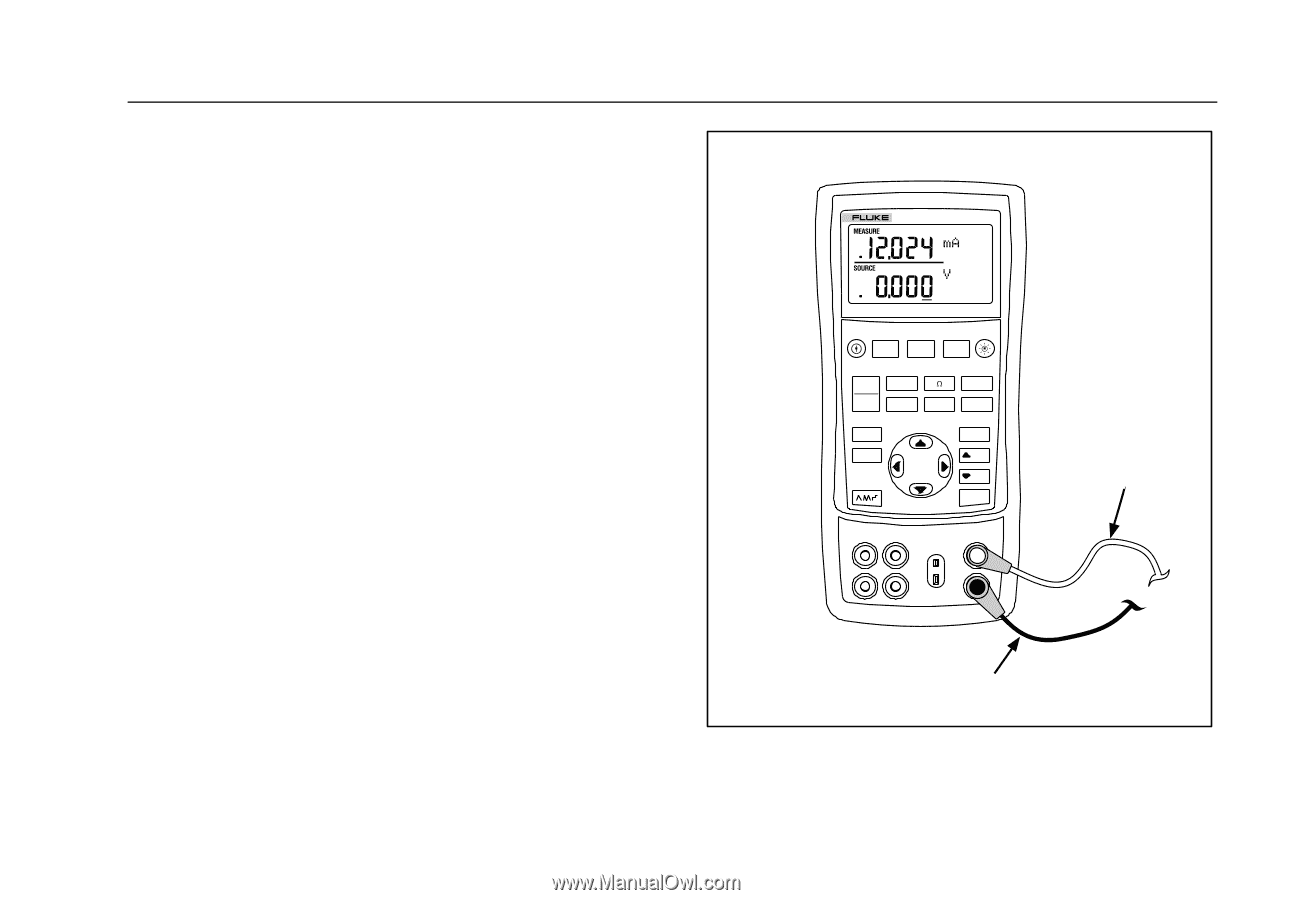
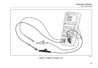
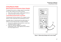
Using Measure Mode Measuring Electrical Parameters (Upper Display) To measure the current or voltage output of a transmitter, use the upper display and proceed as follows: 1. Press A to select current. LOOP should not be on. 2. Connect the leads as shown in Figure 7. Current Measurement with Loop Power The loop power function activates a 24 V supply in series with the current measuring circuit, allowing you to test a transmitter when it is disconnected from plant wiring. To measure current with loop power, proceed as follows: 1. Connect the calibrator to the transmitter current loop terminals as shown in Figure 8. 2. Press K while the calibrator is in current measurement mode. LOOP appears and an internal 24 V loop supply turns on. Temperature Calibrator Using Measure Mode 724 TEMPERATURE CALIBRATOR V mA LOOP MEAS V SOURCE TC STORE SETUP RECALL ˚C RTD ˚F 100% 25% 25% 0% Red Black zi05f.eps Figure 7. Measuring Voltage and Current Output 17
-
 1
1 -
2
-
3
-
4
-
5
-
6
-
7
-
8
-
9
-
10
-
11
-
12
-
13
-
14
-
15
-
16
-
17
-
18
-
19
-
20
-
21
-
 22
22 -
 23
23 -
 24
24 -
 25
25 -
 26
26 -
 27
27 -
 28
28 -
 29
29 -
 30
30 -
 31
31 -
 32
32 -
33
-
34
-
35
-
36
-
37
-
38
-
39
-
40
-
41
-
42
-
43
-
44
-
45
-
46
-
47
-
48
-
49
-
50
-
51
-
52
-
53
-
54
-
55
-
56
 |
 |