Fluke 724 Fluke 724 Users Manual - Page 37
Simulating Thermocouples, Simulating RTDs, wire or 4-wire transmitter, use the stacking - rtd simulation
 |
View all Fluke 724 manuals
Add to My Manuals
Save this manual to your list of manuals |
Page 37 highlights
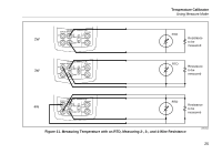
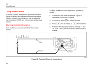
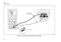
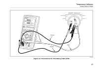
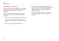
Simulating Thermocouples Connect the calibrator TC input/output to the instrument under test with thermocouple wire and the appropriate thermocouple mini-connector (polarized thermocouple plug with flat, in-line blades spaced 7.9 mm [0.312 in] center to center). Note One pin is wider than the other. Do not try to force a miniplug in the wrong polarization. Figure 13 shows this connection. Proceed as follows to simulate a thermocouple: 1. Attach the thermocouple leads to the appropriate TC miniplug, then to the TC input/output as shown in Figure 13. M 2. If necessary, press for SOURCE mode. 3. Press T for the TC display. If desired, continue pressing this key to select the desired thermocouple type. 4. Enter the temperature you want by pressing X and W keys. Press Y and Z to select a different digit to edit. Temperature Calibrator Using Source Mode Simulating RTDs Connect the calibrator to the instrument under test as shown in Figure 14. Proceed as follows to simulate an RTD: M 1. If necessary, press for SOURCE mode. 2. Press R for the RTD display. Note Use the 3W and 4W terminals for measurement only, not for simulation. The calibrator simulates a 2-wire RTD at its front panel. To connect to a 3-wire or 4-wire transmitter, use the stacking cables to provide the extra wires. See Figure 14. 3. Enter the temperature you want by pressing X and W keys. Press Y and Z to select a different digit to edit. 4. If the 724 display indicates ExI HI the excitation current from your device under test exceeds the limits of the 724. 27
-
 1
1 -
2
-
3
-
4
-
5
-
6
-
7
-
8
-
9
-
10
-
11
-
12
-
13
-
14
-
15
-
16
-
17
-
18
-
19
-
20
-
21
-
22
-
23
-
24
-
25
-
26
-
27
-
28
-
29
-
30
-
31
-
 32
32 -
 33
33 -
 34
34 -
 35
35 -
 36
36 -
 37
37 -
 38
38 -
 39
39 -
 40
40 -
 41
41 -
 42
42 -
43
-
44
-
45
-
46
-
47
-
48
-
49
-
50
-
51
-
52
-
53
-
54
-
55
-
56
 |
 |