Fluke 724 Fluke 724 Users Manual - Page 45
Replacing the Batteries, Replacing the Fuse, and perform the following steps - problems
 |
View all Fluke 724 manuals
Add to My Manuals
Save this manual to your list of manuals |
Page 45 highlights
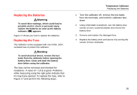
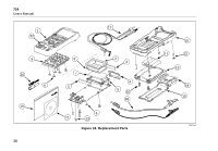
Replacing the Batteries WWarning To avoid false readings, which could lead to possible electric shock or personal injury, replace the batteries as soon as the battery indicator (M) appears. Figure 17 shows you how to replace the batteries. Replacing the Fuse The calibrator comes equipped with one 0.05A, 250V, socketed fuse to protect the calibrator. WWarning To avoid electrical shock, remove the test leads from the calibrator before opening the battery door. Close and latch the battery door before using the calibrator. The fuse can be removed and checked for resistance. A value of < 10 Ω is good. Problems while measuring using the right jacks indicate that F3 may have opened. To replace the fuse, refer to Figure 17 and perform the following steps: Temperature Calibrator Replacing the Batteries 1. Turn the calibrator off, remove the test leads from the terminals, and hold the calibrator face down. 2. Using a flat-blade screwdriver, turn the battery door screws 1/4-turn counterclockwise and remove the battery door. 3. Remove and replace the damaged fuse. 4. Replace the battery door and secure it by turning the screws 1/4-turn clockwise. 35
-
 1
1 -
2
-
3
-
4
-
5
-
6
-
7
-
8
-
9
-
10
-
11
-
12
-
13
-
14
-
15
-
16
-
17
-
18
-
19
-
20
-
21
-
22
-
23
-
24
-
25
-
26
-
27
-
28
-
29
-
30
-
31
-
32
-
33
-
34
-
35
-
36
-
37
-
38
-
39
-
 40
40 -
 41
41 -
 42
42 -
 43
43 -
 44
44 -
 45
45 -
 46
46 -
 47
47 -
 48
48 -
 49
49 -
 50
50 -
51
-
52
-
53
-
54
-
55
-
56
 |
 |