Garmin Edge 510 Owner's Manual - Page 10
Training with Power Meters, Pairing Your ANT+ Sensors - gps bike computer
 |
View all Garmin Edge 510 manuals
Add to My Manuals
Save this manual to your list of manuals |
Page 10 highlights
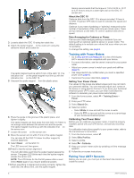
3 Loosely attach the GSC 10 using two cable ties Á. 4 Attach the pedal magnet  to the crank arm using the adhesive mount and a cable tie Ã. The pedal magnet must be within 5 mm of the GSC 10. The indication line Ä on the pedal magnet must line up with the indication line Å on the GSC 10. 5 Unscrew the spoke magnet Æ from the plastic piece. 6 Place the spoke in the groove of the plastic piece, and tighten it slightly. The spoke magnet can face away from the GSC 10 if there is not enough room between the sensor arm and the spoke. The spoke magnet must line up with the indication line Ç on the sensor arm. 7 Loosen the screw È on the sensor arm. 8 Move the sensor arm to within 5 mm of the spoke magnet. You can also tilt the GSC 10 closer to either magnet to improve alignment. 9 Select Reset É on the GSC 10. The LED turns red, then green. 10 Pedal to test the sensor alignment. The red LED blinks each time the pedal magnet passes the sensor. The green LED blinks each time the spoke magnet passes the sensor arm. NOTE: The LED blinks for the first 60 passes after a reset. Select Reset again if you require additional passes. 11When everything is aligned and working correctly, tighten the cable ties, the sensor arm, and the spoke magnet. Garmin recommends that the torque is 1. 9 to 2. 4 lbf-in. (0. 21 to 0. 27 N-m) to ensure a water tight seal on the GSC 10 sensor arm. About the GSC 10 Cadence data from the GSC 10 is always recorded. If there is no GSC 10 paired, GPS data is used to calculate the speed and distance. Cadence is your rate of pedaling or "spinning" measured by the number of revolutions of the crank arm per minute (rpm). There are two sensors on the GSC 10: one for cadence and one for speed. Data Averaging for Cadence or Power The non-zero data-averaging setting is available if you are training with an optional cadence sensor or power meter. The default setting is to exclude zero values that occur when you are not pedaling. To change this setting, see page 8. Training with Power Meters • Go to www.garmin.com/ intosports for a list of third-party ANT + sensors that are compatible with your device. • For more information, see the owner's manual for your power meter. • Adjust your power zones to match your goals and abilities (page 6). • Use range alerts to be notified when you reach a specified power zone (page 3). • Customize the power data fields (page 9). Setting Your Power Zones The values for the zones are default values and may not match your personal abilities. You can manually adjust your zones on the device or using Garmin Connect. If you know your functional threshold power (FTP) value, you can enter it and allow the software to calculate your power zones automatically. 1 From the home screen, select > Training Zones > Power. 2 Enter your FTP value. 3 Select Based On:. 4 Select an option: • Select Watts to view and edit the zones in watts. • Select % FTP to view and edit the zones as a percentage of your functional threshold power. Calibrating Your Power Meter Before you can calibrate your power meter, it must be properly installed, paired with your GPS device, and actively recording data. For calibration instructions specific to your power meter, refer to the manufacturer's instructions. 1 From the home screen, select . 2 Select Bike Profiles. 3 Select a profile. 4 Select > Calibrate. 5 Keep your power meter active by pedaling until the message appears. 6 Follow the on-screen instructions. Pairing Your ANT + Sensors Before you can pair, you must put on the heart rate monitor or install the sensor. 6 ANT+ Sensors
-
 1
1 -
2
-
3
-
4
-
 5
5 -
 6
6 -
 7
7 -
 8
8 -
 9
9 -
 10
10 -
 11
11 -
 12
12 -
 13
13 -
 14
14 -
 15
15 -
16
-
17
-
18
-
19
-
20
 |
 |
