Gigabyte GA-X79-UD5 User Manual - Page 20
Back Panel Connectors, PS/2 Keyboard/Mouse Port - bios reset
 |
View all Gigabyte GA-X79-UD5 manuals
Add to My Manuals
Save this manual to your list of manuals |
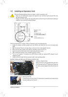
Page 20 highlights
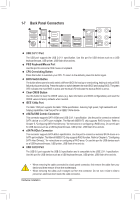
1-7 Back Panel Connectors O.C. USB 2.0/1.1 Port The USB port supports the USB 2.0/1.1 specification. Use this port for USB devices such as a USB keyboard/mouse, USB printer, USB flash drive and etc. PS/2 Keyboard/Mouse Port Use this port to connect a PS/2 mouse or keyboard. CPU Overclcking Button Press this button to overclock your CPU. To return to the defaults, press this button again. BIOS Switch Button The button allows users to easily select a different BIOS for boot up or overclocking, helping to reduce BIOS failure during overclocking. Press the button to switch between the main BIOS and backup BIOS. The green LED indicates the main BIOS is active and the blue LED indicates the backup BIOS is active. Clear CMOS Button Use this button to clear the CMOS values (e.g. date information and BIOS configurations) and reset the CMOS values to factory defaults when needed. IEEE 1394a Port The IEEE 1394 port supports the IEEE 1394a specification, featuring high speed, high bandwidth and hotplug capabilities. Use this port for an IEEE 1394a device. eSATA/USB Combo Connector This connector supports SATA 6Gb/s and USB 2.0/1.1 specification. Use the port to connect an external SATA device or a SATA port multiplier. The Marvell 88SE9172 chip supports RAID function. Refer to Chapter 5, "Configuring SATA Hard Drive(s)," for instructions on configuring a RAID array. Or use this port for USB devices such as a USB keyboard/mouse, USB printer, USB flash drive and etc. eSATA 6Gb/s Connector This connector supports SATA 6Gb/s specification. Use the port to connect an external SATA device or a SATA port multiplier. The Marvell 88SE9172 chip supports RAID function. Refer to Chapter 5, "Configuring SATA Hard Drive(s)," for instructions on configuring a RAID array. Or use this port for USB devices such as a USB keyboard/mouse, USB printer, USB flash drive and etc. USB 3.0/2.0 Port The USB 3.0 port supports the USB 3.0 specification and is compatible to the USB 2.0/1.1 specification. Use this port for USB devices such as a USB keyboard/mouse, USB printer, USB flash drive and etc. •• When removing the cable connected to a back panel connector, first remove the cable from your device and then remove it from the motherboard. •• When removing the cable, pull it straight out from the connector. Do not rock it side to side to prevent an electrical short inside the cable connector. Hardware Installation - 20 -
-
 1
1 -
2
-
3
-
4
-
5
-
6
-
7
-
8
-
9
-
10
-
11
-
12
-
13
-
14
-
 15
15 -
 16
16 -
 17
17 -
 18
18 -
 19
19 -
 20
20 -
 21
21 -
 22
22 -
 23
23 -
 24
24 -
 25
25 -
26
-
27
-
28
-
29
-
30
-
31
-
32
-
33
-
34
-
35
-
36
-
37
-
38
-
39
-
40
-
41
-
42
-
43
-
44
-
45
-
46
-
47
-
48
-
49
-
50
-
51
-
52
-
53
-
54
-
55
-
56
-
57
-
58
-
59
-
60
-
61
-
62
-
63
-
64
-
65
-
66
-
67
-
68
-
69
-
70
-
71
-
72
-
73
-
74
-
75
-
76
-
77
-
78
-
79
-
80
-
81
-
82
-
83
-
84
-
85
-
86
-
87
-
88
-
89
-
90
-
91
-
92
-
93
-
94
-
95
-
96
-
97
-
98
-
99
-
100
-
101
-
102
-
103
-
104
-
105
-
106
-
107
-
108
-
109
-
110
-
111
-
112
-
113
-
114
-
115
-
116
 |
 |
