Hayward E-Command 4 Model: ALL MODELS Installation - Page 7
Plumbing - manual
 |
View all Hayward E-Command 4 manuals
Add to My Manuals
Save this manual to your list of manuals |
Page 7 highlights
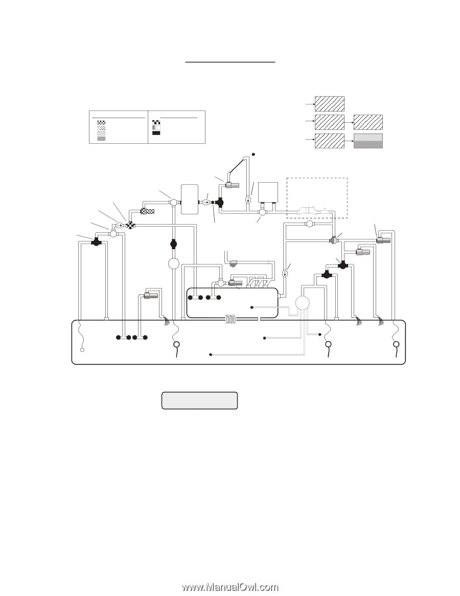
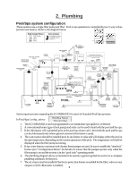
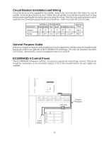
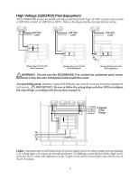
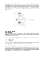
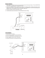
2. Plumbing Pool/Spa system configuration These systems use a single filter pump and filter. Pool or spa operation is controlled by two 3-way valves (suction and return). Refer to the diagram below. HIGH VOLTAGE LIGHTS High Voltage Relays Filter Pump Lights Aux 1 Aux 2 Valve Outputs Pool/Spa Suction Pool/Spa Return Valve 3 TRANSFORMER LOW VOLTAGE LIGHTS FIBER OPTIC LIGHT SOURCE COLOR WHEEL POOL/SPA SUCTION VALVE CHECK VALVE (prevents draining of raised spas) FILTER PUMP MANUAL VALVE MANUAL VALVE POOL VACUUM VALVE TWO-WAY VALVE ENERGY FILTER ISOLATED WATER FEATURE PUMP SOLAR BOOST PUMP FILTER CHECK VALVE SOLAR VALVE SOLAR TEMPERATURE SENSOR CHECK VALVE HEATER if optional Aqua Rite or Swimpure external chlorination control is used FLOW CELL SWITCH POOL/SPA TEMPERATURE SENSOR HEATER BYPASS VALVE (manual) SPA BLOWER MANUAL VALVE POOL SWEEP BOOST PUMP POOL/SPA RETURN VALVE CHECK VALVE (prevents draining of raised spas) WATER FEATURE VALVE WATER FEATURE PUMP SPA JET PUMP SPA POP-UP IN-FLOOR CLEANER SKIM SUCTION CLEANER MAIN DRAIN ENERGY SAVER PRESSURE CLEANER SPILLOVER POOL OVERFLOW POP-UP POP-UP POP-UP RETURN JET VALVE WATER FEATURE PUMP WATER FEATURE NON-BOOST PRESSURE CLEANER PRESSURE CLEANER Some important notes regarding the ECOMMAND 4 control of Standard Pool/Spa systems: In Pool/Spa Config., select: Pool/Spa Setup Pool and Spa 1. The ECOMMAND 4 can be programmed to accommodate spa spillover, if desired. 2. A conventional heater (gas or heat pump) and solar can be used to heat both the pool and the spa. 3. If the chlorinator cell is plumbed prior to the pool/spa return valve, then both the pool and the spa can be chlorinated (only when optional external chlorination is used). 4. The water sensor should be installed prior to any heater or solar and will display either the pool or the spa temperature, depending on the current operation of the pool. The temperature will only be displayed when the filter pump is running. 5. If any water feature or pressure side cleaner boost pumps are used, be sure to enable the "interlock" feature (see "Configuration Menu" for details) to ensure that the pumps operate only when the filter pump is on and the system is in the "pool only" operating mode. 6. The plumbing diagram above is intended to be used as a general guideline and is not a complete plumbing schematic for the pool. 7. The air sensor must be installed if the freeze protection feature is enabled for the filter, valves or aux outputs or if the chlorinator is enabled. 4
-
 1
1 -
 2
2 -
 3
3 -
 4
4 -
 5
5 -
 6
6 -
 7
7 -
 8
8 -
 9
9 -
 10
10 -
 11
11 -
 12
12 -
13
-
14
-
15
-
16
-
17
-
18
-
19
-
20
-
21
-
22
-
23
-
24
-
25
-
26
-
27
-
28
-
29
-
30
-
31
-
32
 |
 |