Hayward OmniLogic Installation Manual
Hayward OmniLogic Manual
 |
View all Hayward OmniLogic manuals
Add to My Manuals
Save this manual to your list of manuals |
Hayward OmniLogic manual content summary:
- Hayward OmniLogic | Installation Manual - Page 1
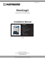
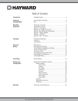
092472 RevA OmniLogic Automation and Chlorination Installation Manual Contents Before You Begin 1 Overview 1 Preparing Pool/Spa Water..........4 Mounting Equipment 6 Plumbing 9 Wiring 13 System Startup 23 Configuration Wizard 24 HLBASE Hayward Pool Products 620 Division Street, Elizabeth NJ - Hayward OmniLogic | Installation Manual - Page 2
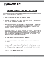
be connected to the grounding means provided in the electrical supply service panel with a continuous copper wire equivalent in size the circuit conductors supplying this equipment. • WARNING: Disconnect all AC power during installation. • WARNING: Water in excess of 100 degrees Fahrenheit may be - Hayward OmniLogic | Installation Manual - Page 3
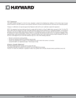
modifications not expressly approved by Hayward could void the user's authority installation. This equipment generates, uses and can radiate radio frequency energy and, if not installed and used in accordance with the instructions registration number only signifies that the Industry Canada technical - Hayward OmniLogic | Installation Manual - Page 4
Service 14 Wiring Grounding and Bonding 14 Circuit Breaker Installation and Wiring 14 General Purpose Outlet 14 OmniLogic Power 14 Pool Equipment Connection Table 15 High Voltage Pool 33 Warranty OmniLogic Limited Warranty 35 USE ONLY HAYWARD GENUINE REPLACEMENT PARTS - Hayward OmniLogic | Installation Manual - Page 5
, the OmniLogic gives the user complete control over both automation and chlorination of their pool and spa. Although the OmniLogic is easy to use, it is important to completely read through this manual before attempting to install, configure or operate the unit. 1 USE ONLY HAYWARD GENUINE - Hayward OmniLogic | Installation Manual - Page 6
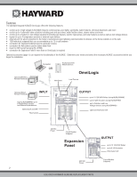
Features The standard Hayward HLBASE OmniLogic offers the following features: • control up to 4 high voltage (120/240V) relays to control pumps, pool lights, yard lights, water features, chemical dispensers and more • control up to 4 automatic valve actuators including pool and spa valves, water - Hayward OmniLogic | Installation Manual - Page 7
Wiring (page 13) Main service Grounding and bonding Circuit breakers OmniLogic power High Voltage pool equipment Low voltage wiring (temperature sensors, flow switch, etc.) 5. System Startup and checkout (page 24) NOTE: If replacing a Pro Logic Controller using networked ColorLogic Lights, the - Hayward OmniLogic | Installation Manual - Page 8
the OmniLogic's optional chlorinator function. NOTE: If the pool does not have new water, add metal remover and non-copper based algaecide to the pool, per manufacturer's instructions. This ensures a quick, troublefree transfer to the OmniLogic system. 4 USE ONLY HAYWARD GENUINE REPLACEMENT - Hayward OmniLogic | Installation Manual - Page 9
pool size is unknown. The operating salt level is between 2700-3400 PPM (parts per million) with 3200 PPM being optimal. Before adding any salt, test the salt level. This is especially important for retrofit installation to older pools the OmniLogic to stop chlorinating. The salt in your pool/spa - Hayward OmniLogic | Installation Manual - Page 10
temperature sensors, as well as optional accessories like Hayward TurboCells and actuators are all 15 ft. (5m) long. The OmniLogic weighs close to 60lbs. and will require two people to position and install. Select the proper location and mounting hardware given the size and weight of the unit. The - Hayward OmniLogic | Installation Manual - Page 11
Three sensors are included with the OmniLogic. A water sensor and an air sensor must be installed at all times for proper operation. Sensor This sensor is used to measure the pool/spa temperature and is installed in the filtration plumbing after the filter but ONLY HAYWARD GENUINE REPLACEMENT PARTS - Hayward OmniLogic | Installation Manual - Page 12
AQL-CHEM2 manual for specific installation information. Wired Remote Terminal Hayward offers an optional wired remote terminals for the OmniLogic, giving you the ability to control your pool's functions from a remote location, away from the pool pad. The OmniLogic can also be controlled remotely by - Hayward OmniLogic | Installation Manual - Page 13
CLEANER Some important notes regarding standard Pool/Spa systems: 1. The OmniLogic can be programmed to accommodate spa spillover, if pool. 7. The air sensor must be installed if the freeze protection feature is enabled for the filter, valves, chlorinator, other pool functions. 9 USE ONLY HAYWARD - Hayward OmniLogic | Installation Manual - Page 14
BYPASS VALVE (manual) SPA BLOWER POOL SWEEP BOOST PUMP POOL/SPA SPILLOVER OmniLogic can be programmed to accommodate spillover if desired. Note that spillover operation will be automatically suspended whenever the spa filter pump is turned on. 5. The chlorinator cell must be installed in the pool - Hayward OmniLogic | Installation Manual - Page 15
cell and flow switch must be installed in the heater return path. If spillover is enabled, then the OmniLogic can chlorinate both the pool and spa (during spillover operation). Otherwise, the OmniLogic will only chlorinate the pool when the spa does not control the heater(s) and the spa sanitization - Hayward OmniLogic | Installation Manual - Page 16
installer). Flow Switch (supplied with P-KIT) A Hayward OmniLogic starts to generate chlorine or dispenses acid. The flow switch must be plumbed in the same section of plumbing as the TurboCell. Failure to properly install the flow switch can result in explosive gases accumulating in the pool - Hayward OmniLogic | Installation Manual - Page 17
power to the Control Center. Always: -Ensure that Power is disconnected prior to performing any wiring -Follow all local and NEC (CEC if applicable) codes -Use copper conductors only -Remove power to the OmniLogic subpanel before removing the deadfront 13 USE ONLY HAYWARD GENUINE REPLACEMENT PARTS - Hayward OmniLogic | Installation Manual - Page 18
OmniLogic control relays or circuit breakers. The OmniLogic should also be connected to the pool bonding system by an 8AWG (6AWG for Canada) wire. A lug for bonding (2 for Canada) is provided on the outside/bottom of the OmniLogic enclosure. Circuit Breaker Installation and Wiring Circuit breakers - Hayward OmniLogic | Installation Manual - Page 19
an HLRELAYBANK, HLIOEXPAND or HLRELAY(s) (see Accessories) . When wiring pool equipment to the OmniLogic, keep a record of all connections. You'll need to record . After attaching a equipment to the OmniLogic, fill in the appropriate information in the table. Connection Table HVR5 HVR8 HVR6 HVR7 15 - Hayward OmniLogic | Installation Manual - Page 20
Record all connections using the table on page 15. ! WARNING: Do not use the OmniLogic to control an automatic pool cover. Swimmers may become entrapped underneath the cover. Two speed filter pump Requires two relays to relays outside of the Relay Bank. 16 USE ONLY HAYWARD GENUINE REPLACEMENT PARTS - Hayward OmniLogic | Installation Manual - Page 21
wiring. Refer to the VSP manual(s) for detailed wiring information. pH Dispense Output When used with a Hayward HL-CHEM, a pH dispensing device may be used. The HL-CHEM is an ORP and pH sensing kit that is offered as an accessory for OmniLogic pool automation controls. The HL-CHEM continuously tests - Hayward OmniLogic | Installation Manual - Page 22
manuals supplied with most heaters also include specific wiring instructions for connecting the heater to an external control (usually identified as "2-wire" remote control). For millivolt or line voltage heaters, contact Hayward Tech support terminal block. 3. Wire OmniLogic to the heater as shown - Hayward OmniLogic | Installation Manual - Page 23
Hayward Heaters Refer to the instructions in the heater manual for "2-wire Remote Thermostat" operation under "Remote Control Connections" and the diagram below: 1. Turn off power to heater. 2. Wire OmniLogic to terminals 1 & 2 (see diagram). 3. Leave jumper attached to terminals 4 & 5. 4. Move " - Hayward OmniLogic | Installation Manual - Page 24
is a mistake, change the mode to "POOL" or "SPA" which then disables the remote control by the OmniLogic. To prevent this: Remove the heater touch pad control box. 3. Remove the jumper for the "fireman's switch. 4. Wire to the OmniLogic using wire rated for 105°C minimum. 20 USE ONLY HAYWARD - Hayward OmniLogic | Installation Manual - Page 25
cable is required, contact the Hayward service dept. (908-355-7995) OmniLogic (see Configuration Wizard in Operation Manual), the filter pump and/or desired pool component will be forced on or off when the device is active. Record all connections using the table on page 15. 21 USE ONLY HAYWARD - Hayward OmniLogic | Installation Manual - Page 26
wired remote terminal to the OmniLogic's High Speed Bus as shown below. Note that the screw connections on both the OmniLogic main unit and the wired remote main PCB in the OmniLogic Control Center as shown below. Refer to the HLCHEM manual for complete installation instructions. Connect Probe Cell - Hayward OmniLogic | Installation Manual - Page 27
as well as a power connection to the OmniLogic's Main Board. Refer to the HLWLAN manual for detailed installation instructions. System Startup Before Startup Before starting the OmniLogic for the first time, be sure that the following items have been completed: 1. Pool/spa chemicals are within the - Hayward OmniLogic | Installation Manual - Page 28
little instruction. the OmniLogic. POOL configuration POOL configuration If additional pool Guide As you progress through the Configuration Wizard, refer to the following information to help answer questions and make selections. Select a Language - The OmniLogic supports OmniLogic is connected to the - Hayward OmniLogic | Installation Manual - Page 29
instructions on how to do this, refer the HLWLAN manual. How many Bodies of Water? The OmniLogic can support one or two bodies of water, typically a pool Size of Pool - Enter the pool size in gallons. If you're not certain the size of your pool, refer to the chart below to help determine the pool - Hayward OmniLogic | Installation Manual - Page 30
selected: Which Hayward Unique Address? If using a VSP, you'll be asked what is the Hayward Unique Address manual for more information. Minimum Allowed Pump Speed % / Maximum Allowed Pump Speed % - The OmniLogic more than 20 minutes, the OmniLogic will shut down the pool pump and will indicate an - Hayward OmniLogic | Installation Manual - Page 31
whether the solar heating system has a dedicated recirculation pump. If so, the OmniLogic will turn this pump on when the pool temperature is below the heater setting and there is solar heat available. If Yes to continue solar heater configuration. 27 USE ONLY HAYWARD GENUINE REPLACEMENT PARTS - Hayward OmniLogic | Installation Manual - Page 32
. If the OmniLogic has been chlorinating for more than the selected ORP timeout without reaching the desired level, the chlorinator will turn off and display an alarm. The user must clear the alarm to resume chlorination. Type of Cell? Select the type of Hayward TurboCell that is installed in your - Hayward OmniLogic | Installation Manual - Page 33
, the OmniLogic will continue to run the filter pump regardless of schedule until the pH level in the pool has reached the setpoint. Do You Have a Salt Water Chlorine Generator? (requires Hayward Turbo Cell) If Yes is selected: Type of Cell? Select the type of Hayward TurboCell that is installed in - Hayward OmniLogic | Installation Manual - Page 34
refer to pump configuration), the OmniLogic will turn on the water feature pump to circulate the water. Do you have ColorLogic Lights? Select yes if you are using any type of Hayward ColorLogic pool or spa lights. Note that the OmniLogic can only support 30 USE ONLY HAYWARD GENUINE REPLACEMENT PARTS - Hayward OmniLogic | Installation Manual - Page 35
ColorLogic configuration. Do you have any other Lights? Select yes if the OmniLogic will be controlling other types of pool, spa or outdoor/landscape lighting. If Yes is selected: How Many Relays maximum desired RPM. Refer to your pump manual for more 31 USE ONLY HAYWARD GENUINE REPLACEMENT PARTS - Hayward OmniLogic | Installation Manual - Page 36
to the next screen to continue configuration. Do You Have a Pool Temperature Sensor? Select whether there is a pool temperature sensor wired to the OmniLogic. If Yes is selected: Where is the Sensor Wired? Touching the sensor, then touch the Advance 32 USE ONLY HAYWARD GENUINE REPLACEMENT PARTS - Hayward OmniLogic | Installation Manual - Page 37
Backyard. Select the location where the sensor is installed. What Type of Sensor? Select the type OmniLogic to turn on or to turn off a piece of pool equipment (slave) based on the state of other pool lights independently. An interlock can also control pool equipment based on the state of a temperature - Hayward OmniLogic | Installation Manual - Page 38
will be the master feature that will control the slave interlocked feature. Interlock is Active When Feature is: - This question relates to the master feature. Select the state of the master feature that will activate the interlocked feature. The OmniLogic will summarize the interlock logic. If the - Hayward OmniLogic | Installation Manual - Page 39
the date of installation of the product. To obtain warranty service or repair, please contact the place of purchase or the nearest Hayward authorized warranty service center. For more information on authorized service centers please contact the Hayward Technical Service Support Center (61 Whitecap - Hayward OmniLogic | Installation Manual - Page 40
36 USE ONLY HAYWARD GENUINE REPLACEMENT PARTS - Hayward OmniLogic | Installation Manual - Page 41
37 USE ONLY HAYWARD GENUINE REPLACEMENT PARTS - Hayward OmniLogic | Installation Manual - Page 42
38 USE ONLY HAYWARD GENUINE REPLACEMENT PARTS - Hayward OmniLogic | Installation Manual - Page 43
39 USE ONLY HAYWARD GENUINE REPLACEMENT PARTS - Hayward OmniLogic | Installation Manual - Page 44
INFORMATION OR CONSUMER TECHNICAL SUPPORT, VISIT OUR WEBSITE AT www.hayward.com Hayward is a registered trademark and OmniLogic, AquaRite and Sense & Dispense are trademarks of Hayward Industries, Inc. © 2013 Hayward Industries, Inc. All other trademarks not owned by Hayward are the property of
-
 1
1 -
 2
2 -
 3
3 -
 4
4 -
 5
5 -
 6
6 -
 7
7 -
8
-
9
-
10
-
11
-
12
-
13
-
14
-
15
-
16
-
17
-
18
-
19
-
20
-
21
-
22
-
23
-
24
-
25
-
26
-
27
-
28
-
29
-
30
-
31
-
32
-
33
-
34
-
35
-
36
-
37
-
38
-
39
-
40
-
41
-
42
-
43
-
44
 |
 |
USE ONLY HAYWARD GENUINE REPLACEMENT PARTS
Hayward Pool Products
620 Division Street, Elizabeth NJ 07207
www.hayward.com
OmniLogic
Installation Manual
HLBASE
Contents
Before You Begin
........................
1
Overview
....................................
1
Preparing Pool/Spa Water
..........
4
Mounting Equipment
.................
6
Plumbing
...................................
9
Wiring
.......................................
13
System Startup
.........................
23
Configuration Wizard
................
24
Automation and Chlorination
092472 RevA