Hayward OmniLogic Installation Manual - Page 27
System Startup, Configuration - firmware
 |
View all Hayward OmniLogic manuals
Add to My Manuals
Save this manual to your list of manuals |
Page 27 highlights
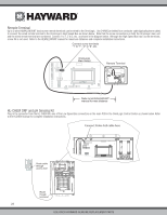
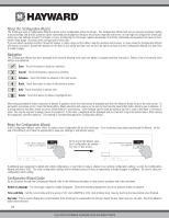
Flow Switch Only applicable if the chlorinator function is enabled and/or if an optional HLCHEM will be used. The flow switch cable plugs into the flow switch connector on the OmniLogic's Main Board as shown on page 13. Ensure that the connector catch "snaps" in order to provide a reliable connection. TurboCell Only applicable if the chlorinator function is enabled. The TurboCell should be plugged in AFTER the OmniLogic cover panel is installed. Refer to page 13 for the location of the connector. HLIOEXPAND The HLIOEXPAND is design to slide between guide rails and insert into a dedicated slot on the OmniLogic main board. At startup, the OmniLogic will discover the HLIOEXPAND and its inputs/outputs can be configured within the OmniLogic's CONFIGURATION WIZARD. Refer to the HLIOEXPANDER manual for installation instructions. HLRELAYBANK Offering four additional high voltage relays, the HLRELAYBANK is a relay kit accessory designed to install next to the four on-board relays in the HLBASE. After installing the HLRELAYBANK, a wire connection must be made at the OmniLogic Main Board. At startup, the OmniLogic will detect the HLRELAYBANK and allow the user to configure the additional relays in the CONFIGURATION WIZARD. Refer to the HLRELAYBANK manual for installation instructions. HLRELAY The HLRELAY is a single high voltage relay designed to be mounted in the #9 and/or #10 positions near the four on-board relays. After installing the HLRELAY, a wire connection must be made at the OmniLogic Main Board. At startup, the OmniLogic will detect the HLRELAY and allow the user to configure the additional relay(s) in the CONFIGURATION WIZARD. Refer to the HLRELAY manual for installation instructions. HLWLAN The HLWLAN can be mounted up to 25ft away from the OmniLogic and requires an ethernet connection to the OmniLogic as well as a power connection to the OmniLogic's Main Board. Refer to the HLWLAN manual for detailed installation instructions. System Startup Before Startup Before starting the OmniLogic for the first time, be sure that the following items have been completed: 1. Pool/spa chemicals are within the recommended levels according to the chart on page 4. 2. Pool/spa salt level is between 2700 - 3400 PPM. 3. Properly rated circuit breakers are installed in the OmniLogic subpanel. 4. All wiring is performed according to NEC and local codes. 5. The OmniLogic is properly grounded and bonded. Configuration Initial Configuration When all input and pool related wiring is complete, replace and secure the deadfront. The OmniLogic can now be powered on for the first time. Apply power at the main panel and wait for the OmniLogic to completely start. This may take a full minute or two. Because this is the first time that the OmniLogic has been powered on, it will bring you directly to the initial configuration screen shown below. Touch the Configuration button in the center of the screen. On the following screen, touch the Configuration Wizard button as shown below. configuration No con g found firmware upgrade 1 / 2 restore config config wizard display system info wired networking backup config web server SYSTEM configuration 23 USE ONLY HAYWARD GENUINE REPLACEMENT PARTS
-
 1
1 -
2
-
3
-
4
-
5
-
6
-
7
-
8
-
9
-
10
-
11
-
12
-
13
-
14
-
15
-
16
-
17
-
18
-
19
-
20
-
21
-
 22
22 -
 23
23 -
 24
24 -
 25
25 -
 26
26 -
 27
27 -
 28
28 -
 29
29 -
 30
30 -
 31
31 -
 32
32 -
33
-
34
-
35
-
36
-
37
-
38
-
39
-
40
-
41
-
42
-
43
-
44
 |
 |
