Hayward OmniLogic Installation Manual - Page 19
Connection Table
 |
View all Hayward OmniLogic manuals
Add to My Manuals
Save this manual to your list of manuals |
Page 19 highlights
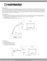
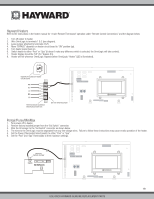
Connection Table The HLBASE includes 4 high voltage relays, 4 low voltage/heater relays, 4 valve outputs and 4 temperature sensor inputs. Additional relays and inputs/outputs can be added using an HLRELAYBANK, HLIOEXPAND or HLRELAY(s) (see Accessories) . When wiring pool equipment to the OmniLogic, keep a record of all connections. You'll need to record which input/output is used and what equipment is attached. To aid in this process, use the table below. To identify the various inputs/outputs, refer to the diagram on the side of the table. After attaching a equipment to the OmniLogic, fill in the appropriate information in the table. Connection Table HVR5 HVR8 HVR6 HVR7 15 USE ONLY HAYWARD GENUINE REPLACEMENT PARTS
-
 1
1 -
2
-
3
-
4
-
5
-
6
-
7
-
8
-
9
-
10
-
11
-
12
-
13
-
 14
14 -
 15
15 -
 16
16 -
 17
17 -
 18
18 -
 19
19 -
 20
20 -
 21
21 -
 22
22 -
 23
23 -
 24
24 -
25
-
26
-
27
-
28
-
29
-
30
-
31
-
32
-
33
-
34
-
35
-
36
-
37
-
38
-
39
-
40
-
41
-
42
-
43
-
44
 |
 |

USE ONLY HAYWARD GENUINE REPLACEMENT PARTS
15
Connection Table
The HLBASE includes 4 high voltage relays, 4 low voltage/heater relays, 4 valve outputs and 4 temperature sensor inputs.
Additional relays and inputs/outputs
can be added using an HLRELAYBANK, HLIOEXPAND or HLRELAY(s) (see Accessories) . When wiring pool equipment to the OmniLogic, keep a record of all
connections.
You’ll need to record which input/output is used and what equipment is attached.
To aid in this process, use the table below.
To identify the vari-
ous inputs/outputs, refer to the diagram on the side of the table.
After attaching a equipment to the OmniLogic, fill in the appropriate information in the table.
HVR5
HVR6
HVR8
HVR7
Connection Table