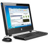
HP 100B Maintenance & Service Guide HP 100B All-in-One
HP 100B - All-in-One PC Manual
 |
View all HP 100B manuals
Add to My Manuals
Save this manual to your list of manuals |
HP 100B manual content summary:
- HP 100B | Maintenance & Service Guide HP 100B All-in-One - Page 1
Maintenance & Service Guide HP 100B All-in-One PC - HP 100B | Maintenance & Service Guide HP 100B All-in-One - Page 2
information that is protected by copyright. No part of this document may be photocopied, reproduced, or translated to another language without the prior written consent of Hewlett-Packard Company. Maintenance & Service Guide HP Compaq 100B All-in-One PC First Edition (January 2011) Document - HP 100B | Maintenance & Service Guide HP 100B All-in-One - Page 3
About This Book WARNING! Text set off in this manner indicates that failure to follow directions could result in bodily harm or loss of life. CAUTION: Text set off in this manner indicates that failure to follow directions could result in damage to equipment or loss of information. NOTE: Text set - HP 100B | Maintenance & Service Guide HP 100B All-in-One - Page 4
iv About This Book - HP 100B | Maintenance & Service Guide HP 100B All-in-One - Page 5
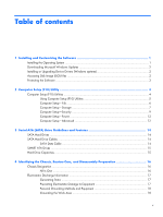
9 Computer Setup-Power 12 Computer Setup-Advanced 12 3 Serial ATA (SATA) Drive Guidelines and Features 14 SATA Hard Drives ...14 SATA Hard Drive Cables ...14 SATA Data Cable 14 SMART ATA Drives ...15 Hard Drive Capacities ...15 4 Identifying the Chassis, Routine Care, and Disassembly Preparation - HP 100B | Maintenance & Service Guide HP 100B All-in-One - Page 6
part number listing 27 6 Removal and Replacement Procedures All-in One (AIO) Chassis 29 Preparing to Disassemble the Computer 29 Rear Cover ...30 Feet ...33 Stand ...34 Optical Drive ...36 Hard Drive ...38 Memory ...42 Fan ...45 Speakers ...48 Webcam Module and Cable 52 Hard Drive Cable - HP 100B | Maintenance & Service Guide HP 100B All-in-One - Page 7
Error Messages 79 POST Numeric Codes and Text Messages 80 Interpreting POST Diagnostic Front Panel LEDs and Audible Codes 87 Appendix B Connector Pin Assignments 91 Ethernet BNC ...91 USB ...91 Microphone ...91 Headphone ...92 Line-in Audio ...92 Line-out Audio ...92 Appendix C Power Cord Set - HP 100B | Maintenance & Service Guide HP 100B All-in-One - Page 8
viii - HP 100B | Maintenance & Service Guide HP 100B All-in-One - Page 9
PROCESS IS COMPLETE. Turning off the computer during the installation process may damage the software that runs the computer or prevent its proper installation. NOTE: If the computer shipped with more than one operating system language on the hard drive, the installation process could take up to 60 - HP 100B | Maintenance & Service Guide HP 100B All-in-One - Page 10
://www.hp.com/support. Select your country and language, select Download drivers and software (and firmware), enter the model number of the computer, and press Enter. Accessing Disk Image (ISO) Files There are disk image files (ISO files) included on your PC that contain the installation software - HP 100B | Maintenance & Service Guide HP 100B All-in-One - Page 11
diagnostic activities on your PC Protecting the Software To protect the software from loss or damage, keep a backup copy of all system software, applications, and related files stored on the hard drive. Refer to the operating system or backup utility documentation for instructions on making backup - HP 100B | Maintenance & Service Guide HP 100B All-in-One - Page 12
they are unsecured. ● Enable or disable removable media boot ability. ● Solve system configuration errors detected but not automatically fixed during the Power-On SelfTest (POST). ● Execute self-tests on a specified ATA hard drive (when supported by drive). 4 Chapter 2 Computer Setup (F10) Utility - HP 100B | Maintenance & Service Guide HP 100B All-in-One - Page 13
will restore the original factory system defaults. CAUTION: Do NOT turn the computer power OFF while the BIOS is saving the Computer Setup (F10) changes because the CMOS could become corrupted. It is safe to turn off the computer only after exiting the F10 Setup screen. Table 2-1 Computer Setup - HP 100B | Maintenance & Service Guide HP 100B All-in-One - Page 14
File NOTE: Support for specific Computer Setup options may vary depending on the hardware configuration. Table 2-2 Computer Setup-File Option Description System Information Lists: ● Product name ● SKU number (some models) ● Processor type/speed/stepping/cache size ● Installed memory size/speed - HP 100B | Maintenance & Service Guide HP 100B All-in-One - Page 15
do not require additional driver support in IDE mode. NOTE: The AHCI device driver must be installed prior to attempting to boot from an AHCI volume. If you attempt to boot from an AHCI volume without the required device driver installed, the system will crash (blue screen). Computer Setup (F10 - HP 100B | Maintenance & Service Guide HP 100B All-in-One - Page 16
selection will only appear when at least one drive capable of performing the DPS selftests is attached to the system. Boot Order Allows you to: ● Specify the order in which attached devices (such as a USB flash media device, hard drive, optical drive, or network interface card) are checked for - HP 100B | Maintenance & Service Guide HP 100B All-in-One - Page 17
Setup-Security NOTE: Support for specific Computer Setup options may vary depending on the hardware configuration. Table 2-4 Computer Setup-Security Option Setup Password Power-On Password Device Security USB Security Slot Security Network Service Boot Description Allows you to set and enable - HP 100B | Maintenance & Service Guide HP 100B All-in-One - Page 18
number is invalid. (These ID numbers are normally set in the factory and are used to uniquely identify the system.) ● SKU number ● Family name ● Feature Allows you to set: ● Keyboard locale setting (for example, English or German) for System ID entry. 10 Chapter 2 Computer Setup (F10) Utility - HP 100B | Maintenance & Service Guide HP 100B All-in-One - Page 19
Device Support (some models) (enable/disable) - Permits activation and deactivation of the Embedded Security Device. Changing this setting requires turning the computer off and then back on. NOTE: To configure the Embedded Security Device, a Setup password must be set. ● Reset to Factory Settings - HP 100B | Maintenance & Service Guide HP 100B All-in-One - Page 20
. This delay is sometimes needed for hard disks on some PCI cards that spin up very slowly, so slowly that they are not ready to boot by the time POST is finished. The POST delay also gives you more time to select F10 to enter Computer (F10) Setup. BIOS Power-On Allows you to set the - HP 100B | Maintenance & Service Guide HP 100B All-in-One - Page 21
speakers). ● NIC Option ROM Download (PXE, Disable, iSCSI). The BIOS contains an embedded NIC option ROM to allow the unit to boot through the network to a PXE server. This is typically used to download a corporate image to a hard drive. The NIC option ROM takes up memory space below 1MB commonly - HP 100B | Maintenance & Service Guide HP 100B All-in-One - Page 22
and Features NOTE: HP only supports the use of SATA hard drives on these models of computer. No Parallel ATA (PATA) drives are supported. SATA Hard Drives Serial ATA Hard Drive Characteristics Number of pins/conductors in data cable Number of pins in power cable Maximum data cable length Data - HP 100B | Maintenance & Service Guide HP 100B All-in-One - Page 23
Analysis and Recording Technology (SMART) ATA drives for the HP Personal Computers have built-in drive failure prediction that warns the user or network administrator of an impending failure or crash of the hard drive. The SMART drive tracks fault prediction and failure indication parameters - HP 100B | Maintenance & Service Guide HP 100B All-in-One - Page 24
, Routine Care, and Disassembly Preparation This chapter provides general service information for the computer. Adherence to the procedures and precautions described in this chapter is essential for proper service. CAUTION: When the computer is plugged into an AC power source, voltage is always - HP 100B | Maintenance & Service Guide HP 100B All-in-One - Page 25
many cases, the discharge contains enough power to alter device parameters or melt Removing DIPs* from plastic tube 400 V Removing DIPs* from vinyl tray 2,000 V Removing DIPs* from Styrofoam 3,500 V Removing . ● Protect all electrostatic parts and assemblies with conductive or approved - HP 100B | Maintenance & Service Guide HP 100B All-in-One - Page 26
types of shoes or boots. On conductive floors or dissipative floor mats, use them on both feet with a maximum of one-megohm ± 10% resistance parts, and assemblies by the case or PCB laminate. Handle them only at static-free work areas. ● Turn off power and input signals before inserting and removing - HP 100B | Maintenance & Service Guide HP 100B All-in-One - Page 27
airflow. ● Occasionally clean the air vents on all vented sides of the computer. Lint, dust, and other foreign matter can block the vents and limit the airflow. Be sure to unplug the computer before cleaning the air vents. ● Never operate the computer with the cover removed. Operating Guidelines 19 - HP 100B | Maintenance & Service Guide HP 100B All-in-One - Page 28
from the computer and keyboard. ● Never cover the ventilation slots on the monitor with any type of material. ● Install or enable power management functions page 20 before cleaning the computer. To clean the computer case, follow the procedures described below: ● To remove light stains or dirt, use - HP 100B | Maintenance & Service Guide HP 100B All-in-One - Page 29
. ● To clean the monitor body follow the procedures in Cleaning the Computer Case on page 20. Cleaning the Mouse Before cleaning the mouse, ensure that the power to the computer is turned off. ● Clean the mouse ball by first removing the retaining plate and the ball from the housing. Pull out any - HP 100B | Maintenance & Service Guide HP 100B All-in-One - Page 30
be caught or snagged by parts being removed or replaced. CAUTION: When servicing this computer, ensure that cables are placed in their proper location during the reassembly process. Improper cable placement can damage the computer. Hard Drives Handle hard drives as delicate, precision components - HP 100B | Maintenance & Service Guide HP 100B All-in-One - Page 31
a hard drive to liquids, temperature extremes, or products that have magnetic fields such as monitors or speakers. Lithium Coin Cell Battery The battery that comes with the computer provides power to the real-time clock and has a minimum lifetime of about three years. See the appropriate removal and - HP 100B | Maintenance & Service Guide HP 100B All-in-One - Page 32
5 Illustrated parts catalog Computer major components 24 Chapter 5 Illustrated parts catalog - HP 100B | Maintenance & Service Guide HP 100B All-in-One - Page 33
foot (7) Optical drive bracket (8) Fan (9) Front bezel (10) Hard drive cable (11) Optical drive cable (12) Heat sink assembly (thermal module) (includes replacement thermal material) (13) Power button board cable (14) WLAN module antenna cable (15) Stand (16) Rear cover (17) Speakers - HP 100B | Maintenance & Service Guide HP 100B All-in-One - Page 34
Memory modules (PC3-10600, 1333-MHz; not illustrated) 4-GB 2-GB 1-GB AC adapter 90W (external; not illustrated) For use worldwide For use in India Keyboard, USB (not illustrated) Brazil Latin America United States Mouse, USB, optical. Portia (not illustrated) Screw Kit (not illustrated) Power cords - HP 100B | Maintenance & Service Guide HP 100B All-in-One - Page 35
-001 Hard drive, 500 GB Hard drive, 750 GB WLAN module (802.11a/b/g/n) System board with AMD dual core processor System board with AMD single core processor AC adapter, 90 W, for use worldwide (external) AC adapter, 90 W, for use in India (external) Front bezel Rear cover Power button board cable - HP 100B | Maintenance & Service Guide HP 100B All-in-One - Page 36
4-GB memory module (PC3-10600, 1333-MHz) 646803-001 8X DVD±RW SuperMulti DL Drive with LightScribe with bezel 646804-001 Optical drive bezel 646805-001 Optical drive bracket 646806-001 WLAN module antenna cable 647448-001 1-GB memory module 647523-001 Screw Kit 28 Chapter 5 Illustrated parts - HP 100B | Maintenance & Service Guide HP 100B All-in-One - Page 37
HP Pro All-in-One. 1. Remove all media (CD, DVD, etc.) from the computer. 2. Shut down the computer. 3. After the system has completely shut down, disconnect the power adapter from the back of the computer. 4. Disconnect all other attached cables from the back of the computer. 5. Place the computer - HP 100B | Maintenance & Service Guide HP 100B All-in-One - Page 38
back. Remove it to gain access to internal components. To remove the rear cover: 1. Prepare the computer for disassembly (see Preparing to Disassemble the Computer on page 29). 2. Lift the stand. Figure 6-1 Lifting the stand 30 Chapter 6 Removal and Replacement Procedures All-in One (AIO) Chassis - HP 100B | Maintenance & Service Guide HP 100B All-in-One - Page 39
3. Remove the five Torx T15M3.0x8.0 screws that secure the rear cover to the computer. Figure 6-2 Removing the rear cover screws 4. Use a flat tool to pry open the slots on the bottom of the computer. Figure 6-3 Prying the rear cover loose Rear Cover 31 - HP 100B | Maintenance & Service Guide HP 100B All-in-One - Page 40
5. Lift the rear cover off the computer. Figure 6-4 Removing the rear cover To replace the rear cover, reverse the removal procedures. 32 Chapter 6 Removal and Replacement Procedures All-in One (AIO) Chassis - HP 100B | Maintenance & Service Guide HP 100B All-in-One - Page 41
under the bracket to remove it, and place it back under the bracket to install it. To remove the feet: 1. Prepare the computer for disassembly (see Preparing to Disassemble the Computer on page 29). 2. Remove the rear cover (see Rear Cover on page 30). 3. For each foot, remove the Torx T15 3.0x6 - HP 100B | Maintenance & Service Guide HP 100B All-in-One - Page 42
Preparing to Disassemble the Computer on page 29). 2. Remove the rear cover (see Rear Cover on page 30). 3. Remove the four Torx T15M4.0x8.0 screws that secure the stand to the rear cover. Figure 6-6 Removing the stand screws 34 Chapter 6 Removal and Replacement Procedures All-in One (AIO) Chassis - HP 100B | Maintenance & Service Guide HP 100B All-in-One - Page 43
4. Lift the stand off the cover. Figure 6-7 Removing the stand To replace the stand, reverse the removal procedures. Stand 35 - HP 100B | Maintenance & Service Guide HP 100B All-in-One - Page 44
with one screw. Figure 6-8 Optical drive location To remove the optical drive: 1. Prepare the computer for disassembly (see Preparing to Disassemble the Computer on page 29). 2. Remove the rear cover (see Rear Cover on page 30). 36 Chapter 6 Removal and Replacement Procedures All-in One (AIO - HP 100B | Maintenance & Service Guide HP 100B All-in-One - Page 45
optical drive to the computer. Figure 6-9 Loosening the drive screw 4. Insert a tool into the slot to push the drive out of the bay, and then slide the drive out of the computer. Figure 6-10 Removing the optical drive To install an optical drive, reverse the removal procedures. Optical Drive 37 - HP 100B | Maintenance & Service Guide HP 100B All-in-One - Page 46
a removable cage. Figure 6-11 Hard drive location To remove the hard drive: 1. Prepare the computer for disassembly (see Preparing to Disassemble the Computer on page 29). 2. Remove the rear cover (see Rear Cover on page 30). 38 Chapter 6 Removal and Replacement Procedures All-in One (AIO) Chassis - HP 100B | Maintenance & Service Guide HP 100B All-in-One - Page 47
3. Loosen the captive screw that secures the drive to the computer. Figure 6-12 Loosening the hard drive screw 4. Slide the drive to the left to disconnect the cables. Figure 6-13 Sliding the hard drive to disconnect the cables Hard Drive 39 - HP 100B | Maintenance & Service Guide HP 100B All-in-One - Page 48
5. Using the drive cage handle, lift the drive out of the computer. Figure 6-14 Removing the hard drive from the computer 40 Chapter 6 Removal and Replacement Procedures All-in One (AIO) Chassis - HP 100B | Maintenance & Service Guide HP 100B All-in-One - Page 49
6. To remove the hard drive from the hard drive cage, remove the four Phillips screws that secure the drive to the cage, and then slide the drive out of the cage. Figure 6-15 Removing the hard drive cage screws Figure 6-16 Removing the hard drive from the hard drive cage To replace the hard drive, - HP 100B | Maintenance & Service Guide HP 100B All-in-One - Page 50
computer has two memory slots. Figure 6-17 Memory location To remove a memory module: 1. Prepare the computer for disassembly (see Preparing to Disassemble the Computer on page 29). 2. Remove the rear cover (see Rear Cover on page 30). 42 Chapter 6 Removal and Replacement Procedures All-in One (AIO - HP 100B | Maintenance & Service Guide HP 100B All-in-One - Page 51
3. Loosen the memory cover screw. Figure 6-18 Removing the memory cover screw 4. Lift the memory cover off the computer. Figure 6-19 Removing the memory cover Memory 43 - HP 100B | Maintenance & Service Guide HP 100B All-in-One - Page 52
20 Removing the memory module Figure 6-21 Removing the memory module NOTE: If you are removing both cards, you must remove the upper one before removing the lower one. To install a memory module, reverse the removal procedures. 44 Chapter 6 Removal and Replacement Procedures All-in One (AIO) Chassis - HP 100B | Maintenance & Service Guide HP 100B All-in-One - Page 53
Fan Description Fan The fan is located at the top of the computer. Figure 6-22 Fan location Spare part number 646798-001 To remove the fan: 1. Prepare the computer for disassembly (see Preparing to Disassemble the Computer on page 29). 2. Remove the rear cover (see Rear Cover on page 30). Fan 45 - HP 100B | Maintenance & Service Guide HP 100B All-in-One - Page 54
3. Disconnect the fan cable from the system board connector. Figure 6-23 Disconnecting the fan cable 4. Remove the four Phillips PM25x60 screws that secure the fan to the computer. Figure 6-24 Removing the fan screws 46 Chapter 6 Removal and Replacement Procedures All-in One (AIO) Chassis - HP 100B | Maintenance & Service Guide HP 100B All-in-One - Page 55
5. Lift the fan out of the computer. Figure 6-25 Removing the fan To install the fan, reverse the removal procedures. Fan 47 - HP 100B | Maintenance & Service Guide HP 100B All-in-One - Page 56
to the system board.. Figure 6-26 Speaker location To remove the speakers: 1. Prepare the computer for disassembly (see Preparing to Disassemble the Computer on page 29). 2. Remove the rear cover (see Rear Cover on page 30). 48 Chapter 6 Removal and Replacement Procedures All-in One (AIO) Chassis - HP 100B | Maintenance & Service Guide HP 100B All-in-One - Page 57
3. Remove two Phillips PM30x100 screws that secure each speaker to the computer. Figure 6-27 Removing the left speaker screws Figure 6-28 Removing the right speaker screws Speakers 49 - HP 100B | Maintenance & Service Guide HP 100B All-in-One - Page 58
4. Remove the left speaker wire from the routing path. Figure 6-29 Removing the left speaker wire 5. Disconnect the speaker cables from the system board connectors. Figure 6-30 Disconnecting the speaker cables from the system board 50 Chapter 6 Removal and Replacement Procedures All-in One (AIO) - HP 100B | Maintenance & Service Guide HP 100B All-in-One - Page 59
6. Lift the speakers from the computer. Figure 6-31 Removing the speakers To install the speakers, reverse the removal procedures. Speakers 51 - HP 100B | Maintenance & Service Guide HP 100B All-in-One - Page 60
the computer for disassembly (see Preparing to Disassemble the Computer on page 29). 2. Remove the rear cover (see Rear Cover on page 30). 3. Disconnect the cable from the webcam module (1) and from the system board (2). 52 Chapter 6 Removal and Replacement Procedures All-in One (AIO) Chassis - HP 100B | Maintenance & Service Guide HP 100B All-in-One - Page 61
lift the cable from the computer. Figure 6-33 Removing the webcam module cable 5. Remove the webcam module cable from the computer. To remove the webcam module: 1. Prepare the computer for disassembly (see Preparing to Disassemble the Computer on page 29). 2. Remove the rear cover (see Rear Cover on - HP 100B | Maintenance & Service Guide HP 100B All-in-One - Page 62
two Phillips PM20x30 screws that secure the module to the bracket, and then remove the module from the bracket. Figure 6-35 Removing the webcam module from the bracket To install a webcam module, reverse the removal procedures. 54 Chapter 6 Removal and Replacement Procedures All-in One (AIO) Chassis - HP 100B | Maintenance & Service Guide HP 100B All-in-One - Page 63
Hard Drive Cable Description Hard drive cable Spare part number 646789-001 The hard drive cable is secured to the computer with two screws and connects the hard drive to the system board. Figure 6-36 Hard drive cable location To remove the hard drive cable: 1. Prepare the computer for disassembly - HP 100B | Maintenance & Service Guide HP 100B All-in-One - Page 64
5. Remove the tape securing the cable to the computer (4), and then lift the connector from the computer. Figure 6-37 Removing the hard drive cable To install the hard drive cable, reverse the removal procedures. 56 Chapter 6 Removal and Replacement Procedures All-in One (AIO) Chassis - HP 100B | Maintenance & Service Guide HP 100B All-in-One - Page 65
to the system board. Figure 6-38 Optical drive cable location To remove the optical drive cable: 1. Prepare the computer for disassembly (see Preparing to Disassemble the Computer on page 29). 2. Remove the rear cover (see Rear Cover on page 30). 3. Remove the two Torx T15M3.0x6.0 screws (1) that - HP 100B | Maintenance & Service Guide HP 100B All-in-One - Page 66
5. Remove the tape securing the cable to the computer, and then lift the connector from the computer. Figure 6-39 Removing the optical drive cable To install the optical drive cable, reverse the removal procedures. 58 Chapter 6 Removal and Replacement Procedures All-in One (AIO) Chassis - HP 100B | Maintenance & Service Guide HP 100B All-in-One - Page 67
by five screws. To remove the optical drive bracket: 1. Prepare the computer for disassembly (see Preparing to Disassemble the Computer on page 29). 2. Remove the rear cover (see Rear Cover on page 30). 3. Remove the optical drive (see Optical Drive on page 36). 4. Remove the five Torx T15M3.0x6 - HP 100B | Maintenance & Service Guide HP 100B All-in-One - Page 68
30). 3. Remove the optical drive (see Optical Drive on page 36). 4. Remove the optical drive bracket (see Optical Drive Bracket on page 59). 5. Remove the two Torx T15M3.0x6.0 screws (1) that secure the board to the computer. 60 Chapter 6 Removal and Replacement Procedures All-in One (AIO) Chassis - HP 100B | Maintenance & Service Guide HP 100B All-in-One - Page 69
to Disassemble the Computer on page 29). 2. Remove the rear cover (see Rear Cover on page 30). 3. Remove the optical drive (see Optical Drive on page 36). 4. Remove the optical drive bracket (see Optical Drive Bracket on page 59). 5. Remove the tape that secures the cable to the computer. Inverter - HP 100B | Maintenance & Service Guide HP 100B All-in-One - Page 70
6. Lift the cable from the computer. Figure 6-43 Removing the inverter board cable To install the inverter board cable, reverse the removal procedures. 62 Chapter 6 Removal and Replacement Procedures All-in One (AIO) Chassis - HP 100B | Maintenance & Service Guide HP 100B All-in-One - Page 71
the computer for disassembly (see Preparing to Disassemble the Computer on page 29). 2. Remove the rear cover (see Rear Cover on page 30). 3. Remove the tape (1) and three screws (2) that secure the board to the computer. NOTE: Note the location of the grounding cables for proper replacement. Power - HP 100B | Maintenance & Service Guide HP 100B All-in-One - Page 72
the computer for disassembly (see Preparing to Disassemble the Computer on page 29). 2. Remove the rear cover (see Rear Cover on page 30). 3. Disconnect the cable from the power button board (1) and the system board (2). 64 Chapter 6 Removal and Replacement Procedures All-in One (AIO) Chassis - HP 100B | Maintenance & Service Guide HP 100B All-in-One - Page 73
(3) that secures the cable to the computer, and then remove the cable from the clip built into the computer (4). Figure 6-46 Removing the power button board cable 5. Remove the cable from the computer. To install the power button board cable, reverse the removal procedures. Power Button Board and - HP 100B | Maintenance & Service Guide HP 100B All-in-One - Page 74
to Disassemble the Computer on page 29). 2. Remove the rear cover (see Rear Cover on page 30). 3. Disconnect the following cables from the system board: ● WLAN cable ● Inverter cable ● Power button board cable ● Webcam cable 66 Chapter 6 Removal and Replacement Procedures All-in One (AIO) Chassis - HP 100B | Maintenance & Service Guide HP 100B All-in-One - Page 75
4. Remove the five Torx T15M3.0x6.0 screws that secure the shield to the computer. Figure 6-48 Removing the system board shield 5. Lift the shield from the computer. To install the system board shield, reverse the removal procedures. System Board Shield 67 - HP 100B | Maintenance & Service Guide HP 100B All-in-One - Page 76
Heat Sink (Thermal Module) Description Heat sink (thermal module) Spare part number 646799-001 The heat sink is secured with three captive screws. To remove the heat sink: 1. Prepare the computer for disassembly (see Preparing to Disassemble the Computer on page 29). 2. Remove the system board - HP 100B | Maintenance & Service Guide HP 100B All-in-One - Page 77
one antenna connect to the module. The antenna cable routes from the module to the antenna at the top of the computer. Figure 6-50 WLAN module location To remove the WLAN module: 1. Prepare the computer for disassembly (see Preparing to Disassemble the Computer on page 29). 2. Remove the rear cover - HP 100B | Maintenance & Service Guide HP 100B All-in-One - Page 78
then remove the screw (2) that secures the module to the computer. Figure 6-51 Disconnecting the WLAN module 5. Lift the module to a 45-degree angle (3), and then remove it from the system board (4). Figure 6-52 Removing the WLAN module 70 Chapter 6 Removal and Replacement Procedures All-in One (AIO - HP 100B | Maintenance & Service Guide HP 100B All-in-One - Page 79
cable: 1. Prepare the computer for disassembly (see Preparing to Disassemble the Computer on page 29). 2. Remove the rear cover (see Rear Cover on page 30). 3. Remove the system board shield (see System Board Shield on page 66). 4. Disconnect the antenna cable from the module (1), remove the cable - HP 100B | Maintenance & Service Guide HP 100B All-in-One - Page 80
Disassemble the Computer on page 29). 2. Remove the rear cover (see Rear Cover on page 30). 3. Remove the memory modules (see Memory on page 42). 4. Remove the system board shield (see System Board Shield on page 66). 5. Remove the WLAN module (see WLAN Module on page 69). 6. Disconnect all cables - HP 100B | Maintenance & Service Guide HP 100B All-in-One - Page 81
.0x6.0 screws that secure the system board to the computer. Figure 6-54 Removing the system board NOTE: For installation, the system board screw holes are labeled M3. 8. Lift the system board up and out of the computer. To install the system board, reverse the removal procedures. System Board 73 - HP 100B | Maintenance & Service Guide HP 100B All-in-One - Page 82
bezel: 1. Prepare the computer for disassembly (see Preparing to Disassemble the Computer on page 29). 2. Remove the rear cover (see Rear Cover on page 30). 3. Remove the optical drive (see Optical Drive on page 36). 4. Remove the hard drive (see Hard Drive on page 38). 5. Remove the fan (see Fan - HP 100B | Maintenance & Service Guide HP 100B All-in-One - Page 83
15. Remove the eight screws that secure the bezel to the display bracket. Figure 6-55 Removing the front bezel 16. Separate the bezel from the display panel bracket. To replace the front bezel, reverse the removal procedures. Front Bezel 75 - HP 100B | Maintenance & Service Guide HP 100B All-in-One - Page 84
to replace the raw panel. To remove the display panel: 1. Prepare the computer for disassembly (see Preparing to Disassemble the Computer on page 29). 2. Remove the rear cover (see Rear Cover on page 30). 3. Remove the optical drive (see Optical Drive on page 36). 4. Remove the hard drive (see Hard - HP 100B | Maintenance & Service Guide HP 100B All-in-One - Page 85
15. Remove the six screws from the right and left sides of the bracket and remove it from the frame. Figure 6-56 Removing the display panel 16. Remove the two screws that secure the LCD inverter, and then remove it from LCD bracket. Figure 6-57 Removing the inverter Display Panel 77 - HP 100B | Maintenance & Service Guide HP 100B All-in-One - Page 86
17. Remove the four screws from the LCD brackets, and then remove them from the LCD module. Figure 6-58 Removing the brackets To replace the display panel, reverse the removal procedures. 78 Chapter 6 Removal and Replacement Procedures All-in One (AIO) Chassis - HP 100B | Maintenance & Service Guide HP 100B All-in-One - Page 87
during Power-On Self-Test (POST) or computer restart, the probable source of the problem, and steps you can take to resolve the error condition. POST Message Disabled suppresses most system messages during POST, such as memory count and non-error text messages. If a POST error occurs, the screen - HP 100B | Maintenance & Service Guide HP 100B All-in-One - Page 88
> Device Options. Reset the date and time under Control Panel. If the problem persists, replace the RTC battery. See the Hardware Reference Guide for instructions on installing a new battery, or contact an authorized dealer or reseller for RTC battery replacement. 80 Appendix A POST Error Messages - HP 100B | Maintenance & Service Guide HP 100B All-in-One - Page 89
using HP-only memory. 4. Verify proper memory module type. 201-Memory Error RAM failure. 1. Ensure memory modules are correctly installed. 2. Verify proper memory module type. 3. Remove and replace the identified faulty memory module(s). 4. If the error persists after replacing memory modules - HP 100B | Maintenance & Service Guide HP 100B All-in-One - Page 90
the keyboard with computer turned off. 2. Ensure that none of the keys are depressed. 3. Replace the keyboard. 4. Replace the system board. 510-Flash Screen Image Corrupted Flash Screen image has errors. Reflash the system ROM with the latest BIOS image. 511-CPU Fan not Detected CPU fan is - HP 100B | Maintenance & Service Guide HP 100B All-in-One - Page 91
.hp.com/support.) 3. Back up contents and replace hard drive. 1801-Microcode Patch Error Processor is not supported by ROM BIOS. 1. Upgrade BIOS to proper version. 2. Change the processor. 1802-Processor Not Supported Recently installed processor is not supported Install a processor supported - HP 100B | Maintenance & Service Guide HP 100B All-in-One - Page 92
computer. 2. Unplug the power cord, re-seat the memory modules, and reboot the computer. 3. If the memory configuration was recently changed, unplug the power cord, restore the original memory configuration, and reboot the computer. 4. If the error persists, replace the system board. 2211-Memory - HP 100B | Maintenance & Service Guide HP 100B All-in-One - Page 93
key is 1. Reboot the computer. not a valid version for the current ME firmware. 2. If the error persists and system BIOS has been recently updated, restore previous system BIOS version. Otherwise, update the ME firmware version. 3. If the error still persists, replace the system board. 2230 - HP 100B | Maintenance & Service Guide HP 100B All-in-One - Page 94
. Parity Check 2 Parity RAM failure or a PCI/PCIe device is asserting a SERR#. Recommended action 1. Reconnect keyboard with computer turned off. 2. Check connector for bent or missing pins. 3. Ensure that none of the keys are depressed. 4. Replace keyboard. Run Computer Setup and Diagnostic - HP 100B | Maintenance & Service Guide HP 100B All-in-One - Page 95
. 4. If the computer is within an enclosure, ensure that there is proper intake and exhaust ventilation for the enclosure. 5. If a message appears on the screen indicating that a fan is not working, replace the fan. 6. Ensure that the heat sink is properly attached. Red Power LED flashes three - HP 100B | Maintenance & Service Guide HP 100B All-in-One - Page 96
problem is solved. Pre-video memory error. CAUTION: To avoid damage to the DIMMs or the system board, you must unplug the computer power cord before attempting to reseat, install, or remove a DIMM module. 1. Reseat DIMMs. 2. Replace DIMMs one at a time to isolate the faulty module. 3. Replace - HP 100B | Maintenance & Service Guide HP 100B All-in-One - Page 97
iteration but LEDs continue until problem is solved. System powers on but is unable to boot. 1. Unplug the AC power cord from the computer, wait 30 seconds, then plug the power cord back in to the computer. 2. Replace the system board. 3. Replace the processor. Red Power LED flashes ten 10 - HP 100B | Maintenance & Service Guide HP 100B All-in-One - Page 98
. If the problem persists, replace the system board. 5. If the 5V_aux light on the system board is not turned on, remove the expansion cards one at a time until the 5V_aux light on the system board turns on. It the problem persists, replace the power supply. 90 Appendix A POST Error Messages - HP 100B | Maintenance & Service Guide HP 100B All-in-One - Page 99
B Connector Pin Assignments This appendix contains the pin assignments for many computer and workstation connectors. Some of these connectors may not be used on the product being serviced. Ethernet BNC Connector and Icon Pin Signal 1 Data 2 Ground USB Connector and Icon Microphone - HP 100B | Maintenance & Service Guide HP 100B All-in-One - Page 100
Headphone Connector and Icon (1/8" miniphone) Line-in Audio Connector and Icon (1/8" miniphone) Line-out Audio Connector and Icon (1/8" miniphone) Pin 1 (Tip) 2 (Ring) 3 (Shield) Signal Audio_left Power_Right Ground Pin 1 (Tip) 2 (Ring) 3 (Shield) Signal Audio_In_Left Audio_In_Right Ground Pin - HP 100B | Maintenance & Service Guide HP 100B All-in-One - Page 101
C Power Cord Set Requirements The power supplies on some computers have external power switches. The voltage select switch feature on the computer permits it to operate from any line voltage between 100-120 or 220-240 volts AC. Power supplies on those computers that do not have external power - HP 100B | Maintenance & Service Guide HP 100B All-in-One - Page 102
(1) SEV Finland (1) SETI United Kingdom (1) BSI France (1) UTE United States (2) UL Germany (1) VDE 1. The flexible cord must be Type HO5VV-F, 3-conductor, 0.75mm2 conductor size. Power cord set fittings (appliance coupler and wall plug) must bear the certification mark of the agency - HP 100B | Maintenance & Service Guide HP 100B All-in-One - Page 103
A AC adapter spare part numbers audible codes 87 26, 27 B battery disposal 23 beep codes 87 bezel removing 74 spare part number booting options Full Boot 79 Quick Boot 79 25, 27, 74 C cable pinouts SATA data 14 cables hard drive 55 inverter board 60 LVDS 28 optical drive 57 power button board - HP 100B | Maintenance & Service Guide HP 100B All-in-One - Page 104
94 power cords spare part number 26 R rear cover removing 30 spare part number 25, 27, 30 removal and replacement procedures All-in One chassis 29 bezel 74 display panel 76 feet 33 hard drive 38 hard drive cable 55 heat sink 68 inverter board 60 inverter board cable 60 memory 42 optical drive 36
-
 1
1 -
 2
2 -
 3
3 -
 4
4 -
 5
5 -
 6
6 -
 7
7 -
8
-
9
-
10
-
11
-
12
-
13
-
14
-
15
-
16
-
17
-
18
-
19
-
20
-
21
-
22
-
23
-
24
-
25
-
26
-
27
-
28
-
29
-
30
-
31
-
32
-
33
-
34
-
35
-
36
-
37
-
38
-
39
-
40
-
41
-
42
-
43
-
44
-
45
-
46
-
47
-
48
-
49
-
50
-
51
-
52
-
53
-
54
-
55
-
56
-
57
-
58
-
59
-
60
-
61
-
62
-
63
-
64
-
65
-
66
-
67
-
68
-
69
-
70
-
71
-
72
-
73
-
74
-
75
-
76
-
77
-
78
-
79
-
80
-
81
-
82
-
83
-
84
-
85
-
86
-
87
-
88
-
89
-
90
-
91
-
92
-
93
-
94
-
95
-
96
-
97
-
98
-
99
-
100
-
101
-
102
-
103
-
104
 |
 |

Maintenance & Service Guide
HP 100B All-in-One PC